Lenovo NetVista A22 User guide for NetVista 2254, 2256, 2257, 6336, 6337, 6339 - Page 63
To connect an additional IDE CD drive or DVD drive, To connect an additional IDE hard disk drive, Installing a Rope Clip
 |
View all Lenovo NetVista A22 manuals
Add to My Manuals
Save this manual to your list of manuals |
Page 63 highlights
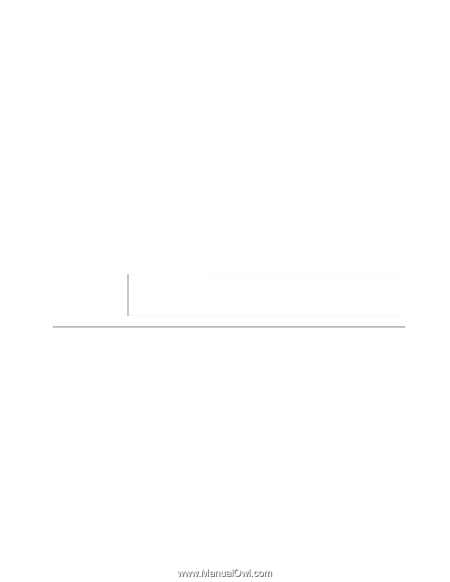
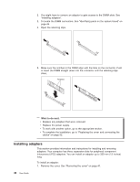
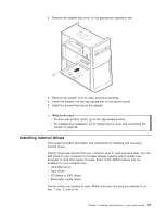
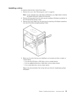
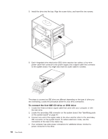
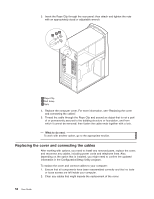
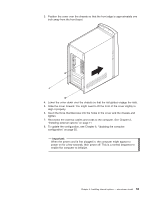
5. If you have a CD-ROM drive audio cable, connect it to the drive and the system board. To connect an additional IDE CD drive or DVD drive 1. Locate the secondary IDE connector on the system board and the three-connector signal cable. See "Identifying parts on the system board" on page 44. 2. Connect the extra connector in the signal cable to the new CD drive or DVD drive. 3. Your computer has extra power connectors for additional drives. Connect a power connector to the drive. To connect an additional IDE hard disk drive 1. You will have to obtain a three-connector signal cable to connect your new hard disk. 2. Remove the two-connector cable from the hard disk drive. 3. Locate the primary IDE connector on the system board. One end of the three-connector cable connects to the hard disk drive and the other connects to the system board. See "Identifying parts on the system board" on page 44. 4. Connect the extra connector in the signal cable to the new hard disk drive. 5. Your computer has extra power connectors for additional drives. Connect a power connector to the drive. What to do next v To work with another option, go to the appropriate section. v To complete the installation, go to "Replacing the cover and connecting the cables" on page 52. Installing a Rope Clip To help prevent hardware theft, you can add a 3/16 inch or 5 mm Rope Clip and cable to your computer. After you add the security cable, make sure that it does not interfere with other cables that are connected to the computer. To install a Rope Clip: 1. Remove cover (see "Removing the cover" on page 41). 2. Use a tool, such as a screwdriver, to remove the two metal knockouts. Chapter 5. Installing internal options - microtower model 51
-
 1
1 -
2
-
3
-
4
-
5
-
6
-
7
-
8
-
9
-
10
-
11
-
12
-
13
-
14
-
15
-
16
-
17
-
18
-
19
-
20
-
21
-
22
-
23
-
24
-
25
-
26
-
27
-
28
-
29
-
30
-
31
-
32
-
33
-
34
-
35
-
36
-
37
-
38
-
39
-
40
-
41
-
42
-
43
-
44
-
45
-
46
-
47
-
48
-
49
-
50
-
51
-
52
-
53
-
54
-
55
-
56
-
57
-
 58
58 -
 59
59 -
 60
60 -
 61
61 -
 62
62 -
 63
63 -
 64
64 -
 65
65 -
 66
66 -
 67
67 -
 68
68 -
69
-
70
-
71
-
72
-
73
-
74
-
75
-
76
-
77
-
78
-
79
-
80
-
81
-
82
-
83
-
84
-
85
-
86
 |
 |