Lenovo PC 300 IBM PC300 (Type 2169) - Hardware Maintenance Manual (September 2 - Page 128
CD2 :AUX_IN. Pin 1 nearest to cpu, JP1 : Clear CMOS. Pin 1 marked on pcb
 |
View all Lenovo PC 300 manuals
Add to My Manuals
Save this manual to your list of manuals |
Page 128 highlights
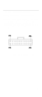
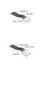
t CPU FAN : CPU cooling FAN Power connector. Pin 1 nearest to cpu Pin No. Function 1 GND. 2 +12V 3 SENSE t CAS FAN: Power FAN Connector. Pin 3 nearest to cpu Pin No. Function 1 GND. 2 +12V 3 SENSE t JP1 : Clear CMOS. Pin 1 marked on pcb Pin No. Function 1-2 close Normal operation (Default). 2-3 close Clear CMOS t CD1: CD Audio Line in. Pin 4 nearest to cpu Pin No. Function 1 CD_L 2,3 GND 4 CD_R t CD2 :AUX_IN. Pin 1 nearest to cpu Pin No. Function 1 AUX_L 2,3 GND 4 AUX_R 126
-
 1
1 -
2
-
3
-
4
-
5
-
6
-
7
-
8
-
9
-
10
-
11
-
12
-
13
-
14
-
15
-
16
-
17
-
18
-
19
-
20
-
21
-
22
-
23
-
24
-
25
-
26
-
27
-
28
-
29
-
30
-
31
-
32
-
33
-
34
-
35
-
36
-
37
-
38
-
39
-
40
-
41
-
42
-
43
-
44
-
45
-
46
-
47
-
48
-
49
-
50
-
51
-
52
-
53
-
54
-
55
-
56
-
57
-
58
-
59
-
60
-
61
-
62
-
63
-
64
-
65
-
66
-
67
-
68
-
69
-
70
-
71
-
72
-
73
-
74
-
75
-
76
-
77
-
78
-
79
-
80
-
81
-
82
-
83
-
84
-
85
-
86
-
87
-
88
-
89
-
90
-
91
-
92
-
93
-
94
-
95
-
96
-
97
-
98
-
99
-
100
-
101
-
102
-
103
-
104
-
105
-
106
-
107
-
108
-
109
-
110
-
111
-
112
-
113
-
114
-
115
-
116
-
117
-
118
-
119
-
120
-
121
-
122
-
 123
123 -
 124
124 -
 125
125 -
 126
126 -
 127
127 -
 128
128 -
 129
129 -
 130
130 -
 131
131 -
 132
132 -
 133
133 -
134
-
135
-
136
-
137
-
138
-
139
-
140
-
141
-
142
-
143
-
144
-
145
-
146
-
147
-
148
-
149
-
150
-
151
-
152
-
153
-
154
-
155
-
156
-
157
 |
 |

126
t
CPU FAN : CPU cooling FAN Power
connector.
Pin 1 nearest to cpu
Pin No.
Function
1
GND.
2
+12V
3
SENSE
t
CAS FAN: Power FAN Connector.
Pin 3
nearest to cpu
Pin No.
Function
1
GND.
2
+12V
3
SENSE
t
JP1 : Clear CMOS. Pin 1 marked on pcb
Pin No.
Function
1-2 close
Normal operation (Default).
2-3 close
Clear CMOS
t
CD1: CD Audio Line in.
Pin 4 nearest to cpu
Pin No.
Function
1
CD_L
2,3
GND
4
CD_R
t
CD2 :AUX_IN. Pin 1 nearest to cpu
Pin No.
Function
1
AUX_L
2,3
GND
4
AUX_R