Lenovo PC 300 IBM PC300 (Type 2169) - Hardware Maintenance Manual (September 2 - Page 129
Panel connectors for switches, AND INDICATORS, Function
 |
View all Lenovo PC 300 manuals
Add to My Manuals
Save this manual to your list of manuals |
Page 129 highlights
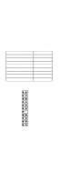
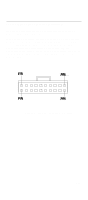
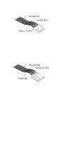
PANEL1: PANEL CONNECTORS FOR SWITCHES AND INDICATORS The panel connector is used to implement the switches and indicators on your system case. Note: Only pins 15, 16 (Hard Disk Indicator) and pins 21, 22 (Power Switch) are used on 2169 standard models. Connector J2, referred to on the system board diagram is used for the power on LED. Function Speaker Power Indicator Keylock Green Indicator Hard Disk Indicator Reset Switch Suspend Switch Power Switch Pins 1, 3, 5, +7 +2, +4, 6 8, 10 +13, 14 +15, 16 17, 18 19, 20 21, 22 22 21 Power SW Suspend SW Reset SW HDD LED Green LED KeyLock Power LED Speaker 2 1 PANEL1 Pins polarity is marked on the pcb next to each pin. To identify which cable connects to the panel 1 pins look at the text on each cable connector: "Power sw" "Hdd led" "Power led" Identifies Power Switch connector Identifies HDD LED connector Identifies Power LED connector 127
-
 1
1 -
2
-
3
-
4
-
5
-
6
-
7
-
8
-
9
-
10
-
11
-
12
-
13
-
14
-
15
-
16
-
17
-
18
-
19
-
20
-
21
-
22
-
23
-
24
-
25
-
26
-
27
-
28
-
29
-
30
-
31
-
32
-
33
-
34
-
35
-
36
-
37
-
38
-
39
-
40
-
41
-
42
-
43
-
44
-
45
-
46
-
47
-
48
-
49
-
50
-
51
-
52
-
53
-
54
-
55
-
56
-
57
-
58
-
59
-
60
-
61
-
62
-
63
-
64
-
65
-
66
-
67
-
68
-
69
-
70
-
71
-
72
-
73
-
74
-
75
-
76
-
77
-
78
-
79
-
80
-
81
-
82
-
83
-
84
-
85
-
86
-
87
-
88
-
89
-
90
-
91
-
92
-
93
-
94
-
95
-
96
-
97
-
98
-
99
-
100
-
101
-
102
-
103
-
104
-
105
-
106
-
107
-
108
-
109
-
110
-
111
-
112
-
113
-
114
-
115
-
116
-
117
-
118
-
119
-
120
-
121
-
122
-
123
-
 124
124 -
 125
125 -
 126
126 -
 127
127 -
 128
128 -
 129
129 -
 130
130 -
 131
131 -
 132
132 -
 133
133 -
 134
134 -
135
-
136
-
137
-
138
-
139
-
140
-
141
-
142
-
143
-
144
-
145
-
146
-
147
-
148
-
149
-
150
-
151
-
152
-
153
-
154
-
155
-
156
-
157
 |
 |
