Lenovo PC 300 IBM PC300 (Type 2169) - Hardware Maintenance Manual (September 2 - Page 81
connectorr. See Power Supply Cable, Table 2-3 Error Symptoms List
 |
View all Lenovo PC 300 manuals
Add to My Manuals
Save this manual to your list of manuals |
Page 81 highlights
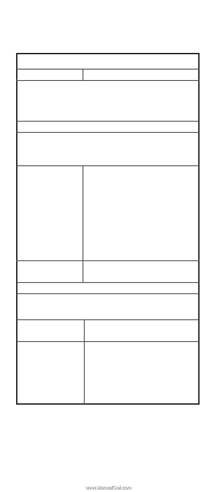
Table 2-3 Error Symptoms List Error Symptoms Action/FRU NOTE: To diagnose a problem, first find the error symptom in the left column. If directed to a check procedure, replace the FRU indicated in the check procedure. If no check procedure is indicated, the first Action/FRU listed in right column is the most likely cause. Processor NOTE: Normally, the processor fan should be operative, and the processor clock setting should be exactly set to match its speed requirement before diagnosing any processor problems. Processor fan does not run but power supply fan runs. Make sure that the system is not in power saving mode. With the system power on, measure the voltage of processor fan connectorr. (See "Power Supply Cable Connector Specifications" on page 129 and refer to the connectors and functions illustrated in chapter 5.) Its reading should be +12Vdc. Processor fan. System board. Processor test failed. Processor. System board. System Board NOTE: Ensure that the memory modules are installed properly and the contact lead is clean before diagnosing any system problems. Memory test failed. "Memory" on page 95 System board Incorrect memory size Insert the memory modules in the shown or repeated DIMM sockets properly, and then during POST. reboot the system. Memory module. See the "Step 005" of "Memory" on page 95 to replace memory module. System board. 79
-
 1
1 -
2
-
3
-
4
-
5
-
6
-
7
-
8
-
9
-
10
-
11
-
12
-
13
-
14
-
15
-
16
-
17
-
18
-
19
-
20
-
21
-
22
-
23
-
24
-
25
-
26
-
27
-
28
-
29
-
30
-
31
-
32
-
33
-
34
-
35
-
36
-
37
-
38
-
39
-
40
-
41
-
42
-
43
-
44
-
45
-
46
-
47
-
48
-
49
-
50
-
51
-
52
-
53
-
54
-
55
-
56
-
57
-
58
-
59
-
60
-
61
-
62
-
63
-
64
-
65
-
66
-
67
-
68
-
69
-
70
-
71
-
72
-
73
-
74
-
75
-
 76
76 -
 77
77 -
 78
78 -
 79
79 -
 80
80 -
 81
81 -
 82
82 -
 83
83 -
 84
84 -
 85
85 -
 86
86 -
87
-
88
-
89
-
90
-
91
-
92
-
93
-
94
-
95
-
96
-
97
-
98
-
99
-
100
-
101
-
102
-
103
-
104
-
105
-
106
-
107
-
108
-
109
-
110
-
111
-
112
-
113
-
114
-
115
-
116
-
117
-
118
-
119
-
120
-
121
-
122
-
123
-
124
-
125
-
126
-
127
-
128
-
129
-
130
-
131
-
132
-
133
-
134
-
135
-
136
-
137
-
138
-
139
-
140
-
141
-
142
-
143
-
144
-
145
-
146
-
147
-
148
-
149
-
150
-
151
-
152
-
153
-
154
-
155
-
156
-
157
 |
 |