Lenovo ThinkCentre A30 Hardware Maintenance Manual (HMM) for ThinkCentre 2296, - Page 38
Removing, cover, Types
 |
View all Lenovo ThinkCentre A30 manuals
Add to My Manuals
Save this manual to your list of manuals |
Page 38 highlights
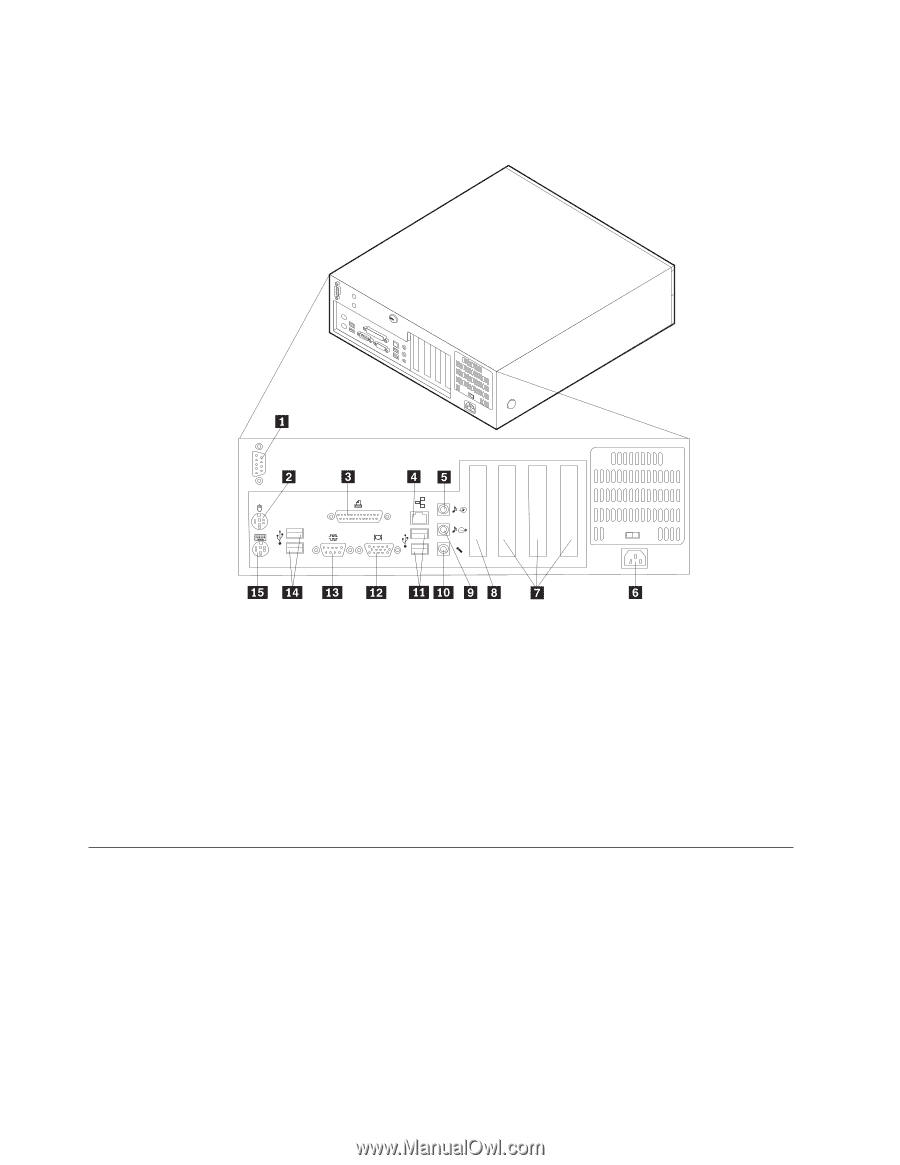
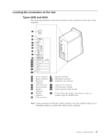
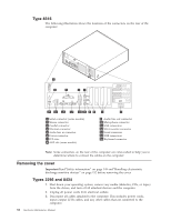
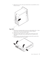
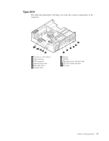
Type 8316 The following illustration shows the locations of the connectors on the rear of the computer. 1 Serial connector (some models) 2 Mouse connector 3 Parallel connector 4 Ethernet connector 5 Audio line in connector 6 Power connector 7 PCI slots 8 AGP slot (some models) 9 Audio line out connector 10 Microphone connector 11 USB connectors 12 VGA monitor connector 13 Serial connector 14 USB connectors 15 Keyboard connector Note: Some connectors on the rear of the computer are color-coded to help you to determine where to connect the cables on the computer. Removing the cover Important:Read"Safety information" on page 149 and"Handling electrostatic discharge-sensitive devices" on page 152 before removing the cover. Types 2296 and 8434 1. Shut down your operating system, remove any media (diskettes, CDs, or tapes) from the drives, and turn off all attached devices and the computer. 2. Unplug all power cords from electrical outlets. 3. Disconnect all cables attached to the computer. This includes power cords, input/output (I/O) cables, and any other cables that are connected to the computer. 32 Hardware Maintenance Manual
-
 1
1 -
2
-
3
-
4
-
5
-
6
-
7
-
8
-
9
-
10
-
11
-
12
-
13
-
14
-
15
-
16
-
17
-
18
-
19
-
20
-
21
-
22
-
23
-
24
-
25
-
26
-
27
-
28
-
29
-
30
-
31
-
32
-
 33
33 -
 34
34 -
 35
35 -
 36
36 -
 37
37 -
 38
38 -
 39
39 -
 40
40 -
 41
41 -
 42
42 -
 43
43 -
44
-
45
-
46
-
47
-
48
-
49
-
50
-
51
-
52
-
53
-
54
-
55
-
56
-
57
-
58
-
59
-
60
-
61
-
62
-
63
-
64
-
65
-
66
-
67
-
68
-
69
-
70
-
71
-
72
-
73
-
74
-
75
-
76
-
77
-
78
-
79
-
80
-
81
-
82
-
83
-
84
-
85
-
86
-
87
-
88
-
89
-
90
-
91
-
92
-
93
-
94
-
95
-
96
-
97
-
98
-
99
-
100
-
101
-
102
-
103
-
104
-
105
-
106
-
107
-
108
-
109
-
110
-
111
-
112
-
113
-
114
-
115
-
116
-
117
-
118
-
119
-
120
-
121
-
122
-
123
-
124
-
125
-
126
-
127
-
128
-
129
-
130
-
131
-
132
-
133
-
134
-
135
-
136
-
137
-
138
-
139
-
140
-
141
-
142
-
143
-
144
-
145
-
146
-
147
-
148
-
149
-
150
-
151
-
152
-
153
-
154
-
155
-
156
-
157
-
158
-
159
-
160
-
161
-
162
-
163
-
164
-
165
-
166
-
167
-
168
-
169
-
170
-
171
-
172
-
173
-
174
-
175
-
176
-
177
-
178
-
179
-
180
-
181
-
182
-
183
-
184
-
185
-
186
-
187
-
188
-
189
-
190
-
191
-
192
 |
 |