Lenovo ThinkCentre A30 Hardware Maintenance Manual (HMM) for ThinkCentre 2296, - Page 46
Identifying, parts, system, board, machine, types, Replacing, memory - front panel
 |
View all Lenovo ThinkCentre A30 manuals
Add to My Manuals
Save this manual to your list of manuals |
Page 46 highlights
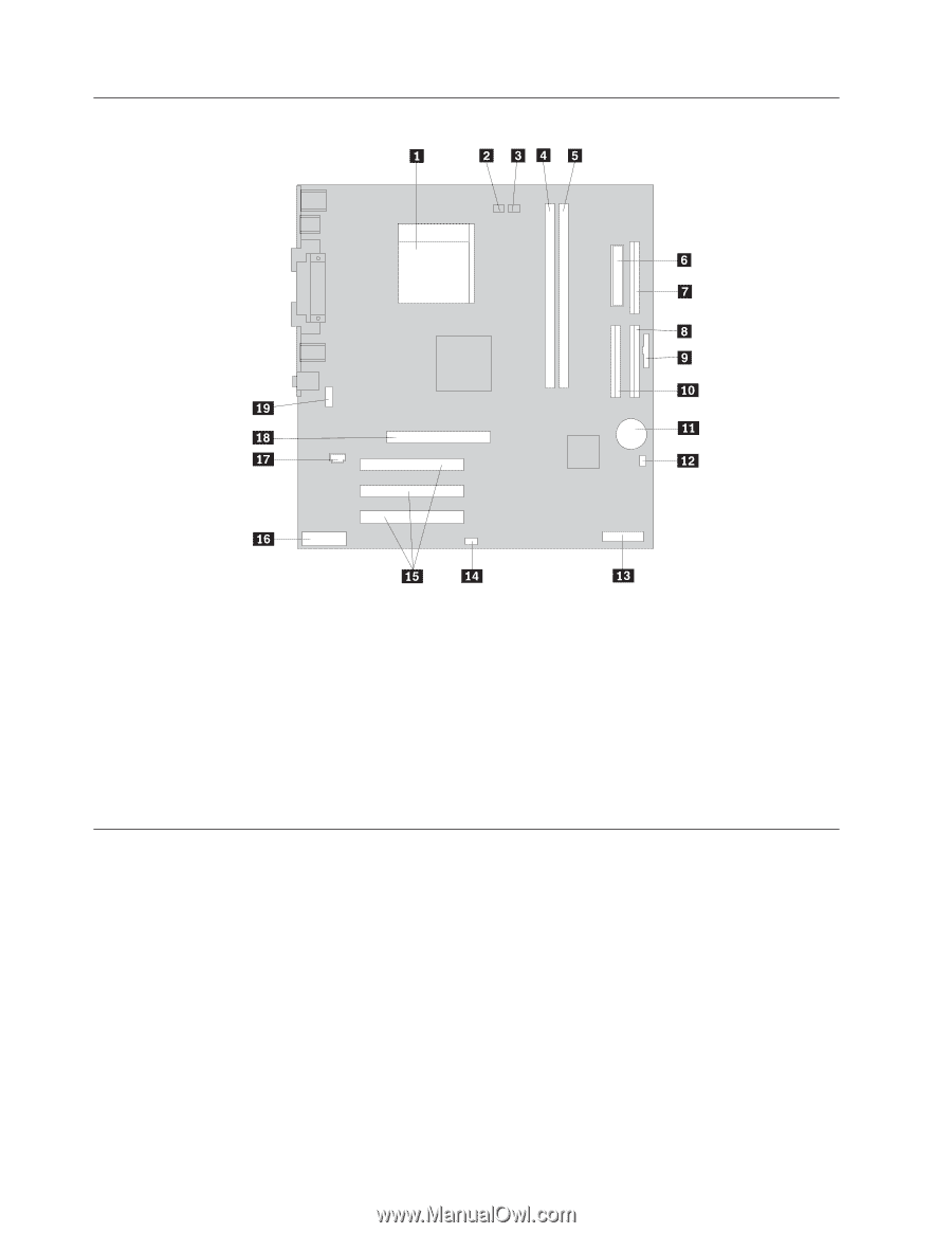
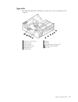
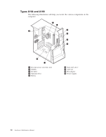
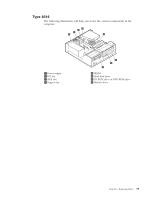
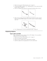
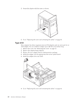
Identifying parts on the system board (all machine types) 1 Microprocessor 2 Rear fan connector 3 Microprocessor fan connector 4 DIMM connector 1 5 DIMM connector 2 6 Power connector 7 Diskette drive 8 Primary IDE connector 9 Front panel connector 10 Secondary IDE connector 11 Battery 12 Clear CMOS/Recovery jumper 13 POV card (some models) 14 SCSI LED connector 15 PCI slots 16 Front panel audio connector 17 CD-ROM audio connector 18 AGP slot (some models) 19 Serial connector Replacing memory (all machine types) The computer has four connectors for installing dual inline memory modules (DIMMs) that provide up to a maximum of 4.0 GB of system memory. When installing DIMMs, the following rules apply: v Fill each DIMM connector sequentially, starting at DIMM connector 1. v Use 2.5 V, 184-pin, 333 MHz double data rate synchronous dynamic random access memory (DDR SDRAM). v Use 128 MB, 256 MB, 512 MB or 1.0 GB DIMMs in any combination. v DIMMs are 38.1 mm (1.5 inches) in height. Note: Only DDR SDRAM DIMMs can be used. To replace a DIMM: 40 Hardware Maintenance Manual
-
 1
1 -
2
-
3
-
4
-
5
-
6
-
7
-
8
-
9
-
10
-
11
-
12
-
13
-
14
-
15
-
16
-
17
-
18
-
19
-
20
-
21
-
22
-
23
-
24
-
25
-
26
-
27
-
28
-
29
-
30
-
31
-
32
-
33
-
34
-
35
-
36
-
37
-
38
-
39
-
40
-
 41
41 -
 42
42 -
 43
43 -
 44
44 -
 45
45 -
 46
46 -
 47
47 -
 48
48 -
 49
49 -
 50
50 -
 51
51 -
52
-
53
-
54
-
55
-
56
-
57
-
58
-
59
-
60
-
61
-
62
-
63
-
64
-
65
-
66
-
67
-
68
-
69
-
70
-
71
-
72
-
73
-
74
-
75
-
76
-
77
-
78
-
79
-
80
-
81
-
82
-
83
-
84
-
85
-
86
-
87
-
88
-
89
-
90
-
91
-
92
-
93
-
94
-
95
-
96
-
97
-
98
-
99
-
100
-
101
-
102
-
103
-
104
-
105
-
106
-
107
-
108
-
109
-
110
-
111
-
112
-
113
-
114
-
115
-
116
-
117
-
118
-
119
-
120
-
121
-
122
-
123
-
124
-
125
-
126
-
127
-
128
-
129
-
130
-
131
-
132
-
133
-
134
-
135
-
136
-
137
-
138
-
139
-
140
-
141
-
142
-
143
-
144
-
145
-
146
-
147
-
148
-
149
-
150
-
151
-
152
-
153
-
154
-
155
-
156
-
157
-
158
-
159
-
160
-
161
-
162
-
163
-
164
-
165
-
166
-
167
-
168
-
169
-
170
-
171
-
172
-
173
-
174
-
175
-
176
-
177
-
178
-
179
-
180
-
181
-
182
-
183
-
184
-
185
-
186
-
187
-
188
-
189
-
190
-
191
-
192
 |
 |