Lenovo ThinkCentre A30 Hardware Maintenance Manual (HMM) for ThinkCentre 2296, - Page 60
Drive, information, Removing, drive
 |
View all Lenovo ThinkCentre A30 manuals
Add to My Manuals
Save this manual to your list of manuals |
Page 60 highlights
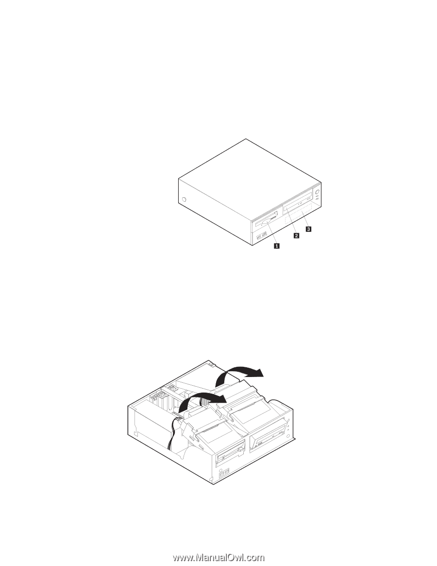
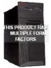
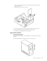
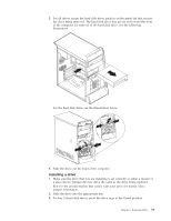
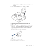
4. If the front bezel was removed, replace it by aligning and pressing the bezel into position. Continue at "Connecting the drive" on page 56. Type 8316 Drive bay information Any bay that does not have a drive installed has a static shield and bay panel installed. The following illustration shows the locations of the drive bays. The following table describes the drive height limitation for each drive bay. Bay 1 and Bay 3 - Maximum height: 25.8 mm (1.0 in.) Bay 2 - Maximum height: 43.0 mm (1.7 in.) Removing a drive 1. Remove the cover. See "Removing the cover" on page 32. 2. Pivot the drive-bay latch handle toward the front of the computer and then pivot the drive-bay cages upward, as shown, until latched in the upright position. 3. Disconnect the signal cable and power supply cable from the drive being replaced. 54 Hardware Maintenance Manual
-
 1
1 -
2
-
3
-
4
-
5
-
6
-
7
-
8
-
9
-
10
-
11
-
12
-
13
-
14
-
15
-
16
-
17
-
18
-
19
-
20
-
21
-
22
-
23
-
24
-
25
-
26
-
27
-
28
-
29
-
30
-
31
-
32
-
33
-
34
-
35
-
36
-
37
-
38
-
39
-
40
-
41
-
42
-
43
-
44
-
45
-
46
-
47
-
48
-
49
-
50
-
51
-
52
-
53
-
54
-
 55
55 -
 56
56 -
 57
57 -
 58
58 -
 59
59 -
 60
60 -
 61
61 -
 62
62 -
 63
63 -
 64
64 -
 65
65 -
66
-
67
-
68
-
69
-
70
-
71
-
72
-
73
-
74
-
75
-
76
-
77
-
78
-
79
-
80
-
81
-
82
-
83
-
84
-
85
-
86
-
87
-
88
-
89
-
90
-
91
-
92
-
93
-
94
-
95
-
96
-
97
-
98
-
99
-
100
-
101
-
102
-
103
-
104
-
105
-
106
-
107
-
108
-
109
-
110
-
111
-
112
-
113
-
114
-
115
-
116
-
117
-
118
-
119
-
120
-
121
-
122
-
123
-
124
-
125
-
126
-
127
-
128
-
129
-
130
-
131
-
132
-
133
-
134
-
135
-
136
-
137
-
138
-
139
-
140
-
141
-
142
-
143
-
144
-
145
-
146
-
147
-
148
-
149
-
150
-
151
-
152
-
153
-
154
-
155
-
156
-
157
-
158
-
159
-
160
-
161
-
162
-
163
-
164
-
165
-
166
-
167
-
168
-
169
-
170
-
171
-
172
-
173
-
174
-
175
-
176
-
177
-
178
-
179
-
180
-
181
-
182
-
183
-
184
-
185
-
186
-
187
-
188
-
189
-
190
-
191
-
192
 |
 |