Lenovo ThinkCentre A30 Hardware Maintenance Manual (HMM) for ThinkCentre 2296, - Page 70
Replacing, cover, connecting, cables, Types
 |
View all Lenovo ThinkCentre A30 manuals
Add to My Manuals
Save this manual to your list of manuals |
Page 70 highlights
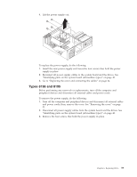
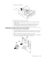
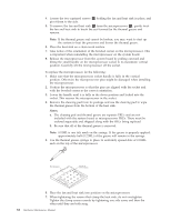
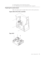
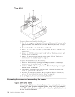
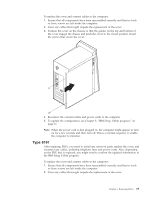
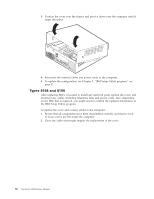
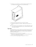
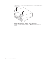
Type 8316 To remove the system board, do the following: 1. Turn off the computer and peripheral devices and disconnect all external cables and power cords; then, remove the cover. See "Removing the cover" on page 32. 2. Disconnect all cables connected to the system board. 3. Remove the screws that secure the system board to the chassis and lift out the system board. 4. Remove the DIMMs from the system board. Refer to "Replacing memory (all machine types)" on page 40. 5. Remove the microprocessor from the system board. Refer to "Replacing a microprocessor (all machine types)" on page 61. To replace the system board, do the following: 1. Install the microprocessor on the new system board. Refer to "Replacing a microprocessor (all machine types)" on page 61. 2. Install the DIMMs on the new system board. Refer to "Replacing memory (all machine types)" on page 40. 3. Place the new the system board into the chassis and install the screws that secure the system board to the chassis. 4. Reconnect all cables that connect to the system board. Refer to "Identifying parts on the system board (all machine types)" on page 40. 5. Go to "Replacing the cover and connecting the cables." Replacing the cover and connecting the cables Types 2296 and 8434 After replacing FRUs, you need to install any removed parts, replace the cover, and reconnect any cables, including telephone lines and power cords. Also, depending on the FRU that is replaced, you might need to confirm the updated information in the IBM Setup Utility program. 64 Hardware Maintenance Manual
-
 1
1 -
2
-
3
-
4
-
5
-
6
-
7
-
8
-
9
-
10
-
11
-
12
-
13
-
14
-
15
-
16
-
17
-
18
-
19
-
20
-
21
-
22
-
23
-
24
-
25
-
26
-
27
-
28
-
29
-
30
-
31
-
32
-
33
-
34
-
35
-
36
-
37
-
38
-
39
-
40
-
41
-
42
-
43
-
44
-
45
-
46
-
47
-
48
-
49
-
50
-
51
-
52
-
53
-
54
-
55
-
56
-
57
-
58
-
59
-
60
-
61
-
62
-
63
-
64
-
 65
65 -
 66
66 -
 67
67 -
 68
68 -
 69
69 -
 70
70 -
 71
71 -
 72
72 -
 73
73 -
 74
74 -
 75
75 -
76
-
77
-
78
-
79
-
80
-
81
-
82
-
83
-
84
-
85
-
86
-
87
-
88
-
89
-
90
-
91
-
92
-
93
-
94
-
95
-
96
-
97
-
98
-
99
-
100
-
101
-
102
-
103
-
104
-
105
-
106
-
107
-
108
-
109
-
110
-
111
-
112
-
113
-
114
-
115
-
116
-
117
-
118
-
119
-
120
-
121
-
122
-
123
-
124
-
125
-
126
-
127
-
128
-
129
-
130
-
131
-
132
-
133
-
134
-
135
-
136
-
137
-
138
-
139
-
140
-
141
-
142
-
143
-
144
-
145
-
146
-
147
-
148
-
149
-
150
-
151
-
152
-
153
-
154
-
155
-
156
-
157
-
158
-
159
-
160
-
161
-
162
-
163
-
164
-
165
-
166
-
167
-
168
-
169
-
170
-
171
-
172
-
173
-
174
-
175
-
176
-
177
-
178
-
179
-
180
-
181
-
182
-
183
-
184
-
185
-
186
-
187
-
188
-
189
-
190
-
191
-
192
 |
 |
