Lenovo ThinkCentre A70z Hardware Maintenance Manual for ThinkCentre A70z - Page 101
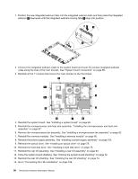
Installing an integrated webcam, Press the integrated webcam-locking tabs
 |
View all Lenovo ThinkCentre A70z manuals
Add to My Manuals
Save this manual to your list of manuals |
Page 101 highlights
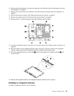
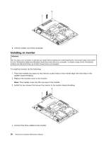
10. Remove the microprocessor and heat sink assembly. See "Removing the microprocessor and heat sink assembly" on page 85. 11. Remove the microprocessor fan assembly. See "Removing the microprocessor fan assembly" on page 81. 12. Remove the memory modules. See "Removing the memory module" on page 79. 13. Remove the system board. See "Removing the system board" on page 88. 14. Remove all the 11 screws that secure the main bracket to the front bezel. 15. Locate the integrated webcam connector on the system board. See "System board connectors" on page 68. 16. Note the location of the integrated webcam cable connection. Note the routing of the integrated webcam cable. Disconnect the integrated webcam cable from the system board. 17. Press the integrated webcam-locking tabs 2 inward to disengage the integrated webcam 1 from the front bezel. 18. Remove the integrated webcam and integrated webcam cable from the computer. Installing an integrated webcam To install an integrated webcam, do the following: Chapter 8. Replacing FRUs 95
-
 1
1 -
2
-
3
-
4
-
5
-
6
-
7
-
8
-
9
-
10
-
11
-
12
-
13
-
14
-
15
-
16
-
17
-
18
-
19
-
20
-
21
-
22
-
23
-
24
-
25
-
26
-
27
-
28
-
29
-
30
-
31
-
32
-
33
-
34
-
35
-
36
-
37
-
38
-
39
-
40
-
41
-
42
-
43
-
44
-
45
-
46
-
47
-
48
-
49
-
50
-
51
-
52
-
53
-
54
-
55
-
56
-
57
-
58
-
59
-
60
-
61
-
62
-
63
-
64
-
65
-
66
-
67
-
68
-
69
-
70
-
71
-
72
-
73
-
74
-
75
-
76
-
77
-
78
-
79
-
80
-
81
-
82
-
83
-
84
-
85
-
86
-
87
-
88
-
89
-
90
-
91
-
92
-
93
-
94
-
95
-
 96
96 -
 97
97 -
 98
98 -
 99
99 -
 100
100 -
 101
101 -
 102
102 -
 103
103 -
 104
104 -
 105
105 -
 106
106 -
107
-
108
-
109
-
110
-
111
-
112
-
113
-
114
-
115
-
116
-
117
-
118
-
119
-
120
-
121
-
122
-
123
-
124
-
125
-
126
-
127
-
128
-
129
-
130
-
131
-
132
-
133
-
134
-
135
-
136
-
137
-
138
-
139
-
140
-
141
-
142
-
143
-
144
-
145
-
146
-
147
-
148
-
149
-
150
-
151
-
152
-
153
-
154
-
155
-
156
-
157
-
158
-
159
-
160
-
161
-
162
-
163
-
164
-
165
-
166
-
167
-
168
-
169
-
170
-
171
-
172
-
173
-
174
-
175
-
176
-
177
-
178
-
179
-
180
-
181
-
182
-
183
-
184
-
185
-
186
-
187
-
188
-
189
-
190
-
191
-
192
-
193
-
194
 |
 |
