Lenovo ThinkCentre A70z Hardware Maintenance Manual for ThinkCentre A70z - Page 95
Installing a system board, the new system board.
 |
View all Lenovo ThinkCentre A70z manuals
Add to My Manuals
Save this manual to your list of manuals |
Page 95 highlights
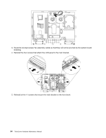
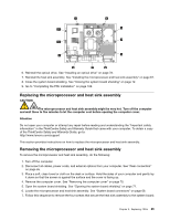
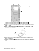
3. Place a soft, clean towel or cloth on the desk or surface. Hold the sides of your computer and gently lay it down so that the screen is against the surface and the cover is facing up. 4. Remove the computer cover. See "Removing the computer cover" on page 70. 5. Open the system board shielding. See "Opening the system board shielding" on page 71. 6. Note the locations of all cable connections on the system board and disconnect all cables. See "System board connectors" on page 68. 7. Remove the microprocessor and heat sink assembly from the system board. See "Removing the microprocessor and heat sink assembly" on page 85. 8. Remove the four screws that attach the system board to the main bracket 1 . 9. Carefully lift the system board out of the chassis. 10. Remove the memory modules from the failing system board and install them in the same locations on the new system board. Installing a system board To install a system board, do the following: 1. Install the new system board into the chassis and align the screw holes with those in the chassis. 2. Insert and tighten the four screws 1 that secure the system board to the main bracket. Chapter 8. Replacing FRUs 89
-
 1
1 -
2
-
3
-
4
-
5
-
6
-
7
-
8
-
9
-
10
-
11
-
12
-
13
-
14
-
15
-
16
-
17
-
18
-
19
-
20
-
21
-
22
-
23
-
24
-
25
-
26
-
27
-
28
-
29
-
30
-
31
-
32
-
33
-
34
-
35
-
36
-
37
-
38
-
39
-
40
-
41
-
42
-
43
-
44
-
45
-
46
-
47
-
48
-
49
-
50
-
51
-
52
-
53
-
54
-
55
-
56
-
57
-
58
-
59
-
60
-
61
-
62
-
63
-
64
-
65
-
66
-
67
-
68
-
69
-
70
-
71
-
72
-
73
-
74
-
75
-
76
-
77
-
78
-
79
-
80
-
81
-
82
-
83
-
84
-
85
-
86
-
87
-
88
-
89
-
 90
90 -
 91
91 -
 92
92 -
 93
93 -
 94
94 -
 95
95 -
 96
96 -
 97
97 -
 98
98 -
 99
99 -
 100
100 -
101
-
102
-
103
-
104
-
105
-
106
-
107
-
108
-
109
-
110
-
111
-
112
-
113
-
114
-
115
-
116
-
117
-
118
-
119
-
120
-
121
-
122
-
123
-
124
-
125
-
126
-
127
-
128
-
129
-
130
-
131
-
132
-
133
-
134
-
135
-
136
-
137
-
138
-
139
-
140
-
141
-
142
-
143
-
144
-
145
-
146
-
147
-
148
-
149
-
150
-
151
-
152
-
153
-
154
-
155
-
156
-
157
-
158
-
159
-
160
-
161
-
162
-
163
-
164
-
165
-
166
-
167
-
168
-
169
-
170
-
171
-
172
-
173
-
174
-
175
-
176
-
177
-
178
-
179
-
180
-
181
-
182
-
183
-
184
-
185
-
186
-
187
-
188
-
189
-
190
-
191
-
192
-
193
-
194
 |
 |
