Lenovo ThinkCentre A70z Hardware Maintenance Manual for ThinkCentre A70z - Page 71
Replacing FRUs, Locating controls and connectors on the front of your computer
 |
View all Lenovo ThinkCentre A70z manuals
Add to My Manuals
Save this manual to your list of manuals |
Page 71 highlights
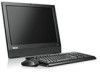
Chapter 8. Replacing FRUs Important Before you replace any FRU, read Chapter 2 "Safety information" on page 3. These precautions and guidelines will help you work safely. FRU replacements are to be done by trained service technicians only. This chapter does not contain a removal and replacement procedure for all FRUs. Only the major FRUs are documented. Locating controls and connectors on the front of your computer The following illustration shows the locations of the controls and connectors on the front of your computer. 1 Integrated camera (available in some models) 2 Integrated microphone 3 Brightness controls 4 USB connectors (3) 5 Headphone connector 6 Microphone connector 7 Power switch 8 Power indicator light-emitting diode (LED) 9 Internal speakers (2) Rear connectors The following illustration shows the locations of the connectors on the rear of the computer. © Copyright Lenovo 2009, 2012 65
-
 1
1 -
2
-
3
-
4
-
5
-
6
-
7
-
8
-
9
-
10
-
11
-
12
-
13
-
14
-
15
-
16
-
17
-
18
-
19
-
20
-
21
-
22
-
23
-
24
-
25
-
26
-
27
-
28
-
29
-
30
-
31
-
32
-
33
-
34
-
35
-
36
-
37
-
38
-
39
-
40
-
41
-
42
-
43
-
44
-
45
-
46
-
47
-
48
-
49
-
50
-
51
-
52
-
53
-
54
-
55
-
56
-
57
-
58
-
59
-
60
-
61
-
62
-
63
-
64
-
65
-
 66
66 -
 67
67 -
 68
68 -
 69
69 -
 70
70 -
 71
71 -
 72
72 -
 73
73 -
 74
74 -
 75
75 -
 76
76 -
77
-
78
-
79
-
80
-
81
-
82
-
83
-
84
-
85
-
86
-
87
-
88
-
89
-
90
-
91
-
92
-
93
-
94
-
95
-
96
-
97
-
98
-
99
-
100
-
101
-
102
-
103
-
104
-
105
-
106
-
107
-
108
-
109
-
110
-
111
-
112
-
113
-
114
-
115
-
116
-
117
-
118
-
119
-
120
-
121
-
122
-
123
-
124
-
125
-
126
-
127
-
128
-
129
-
130
-
131
-
132
-
133
-
134
-
135
-
136
-
137
-
138
-
139
-
140
-
141
-
142
-
143
-
144
-
145
-
146
-
147
-
148
-
149
-
150
-
151
-
152
-
153
-
154
-
155
-
156
-
157
-
158
-
159
-
160
-
161
-
162
-
163
-
164
-
165
-
166
-
167
-
168
-
169
-
170
-
171
-
172
-
173
-
174
-
175
-
176
-
177
-
178
-
179
-
180
-
181
-
182
-
183
-
184
-
185
-
186
-
187
-
188
-
189
-
190
-
191
-
192
-
193
-
194
 |
 |
