Lenovo ThinkCentre A70z Hardware Maintenance Manual for ThinkCentre A70z - Page 93
Installing the microprocessor and heat sink assembly, in the socket.
 |
View all Lenovo ThinkCentre A70z manuals
Add to My Manuals
Save this manual to your list of manuals |
Page 93 highlights
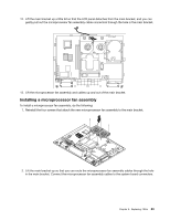
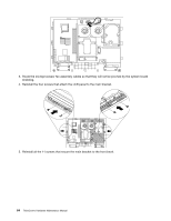
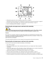
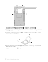
Installing the microprocessor and heat sink assembly To install a microprocessor and heat sink assembly, do the following: 1. Touch the static-protective package that contains the new microprocessor to any unpainted metal surface on the computer; remove the microprocessor from the package. 2. Align the microprocessor 1 with the socket (note the alignment mark 2 and the position of the notches 3 ); carefully place the microprocessor on the socket and close the microprocessor bracket frame. Note: The microprocessor fits only one way on the socket. 3. Carefully close the microprocessor release lever 4 to the closed position to secure the microprocessor in the socket. 4. Clean the grease from the heat sink assembly and apply new grease on the microprocessor. 5. Align the heat sink assembly on top of the microprocessor, and make sure the four screws in the heat sink align with the holes in the system board. 6. Follow this sequence to install the four screws that secure the heat sink assembly to the system board: Chapter 8. Replacing FRUs 87
-
 1
1 -
2
-
3
-
4
-
5
-
6
-
7
-
8
-
9
-
10
-
11
-
12
-
13
-
14
-
15
-
16
-
17
-
18
-
19
-
20
-
21
-
22
-
23
-
24
-
25
-
26
-
27
-
28
-
29
-
30
-
31
-
32
-
33
-
34
-
35
-
36
-
37
-
38
-
39
-
40
-
41
-
42
-
43
-
44
-
45
-
46
-
47
-
48
-
49
-
50
-
51
-
52
-
53
-
54
-
55
-
56
-
57
-
58
-
59
-
60
-
61
-
62
-
63
-
64
-
65
-
66
-
67
-
68
-
69
-
70
-
71
-
72
-
73
-
74
-
75
-
76
-
77
-
78
-
79
-
80
-
81
-
82
-
83
-
84
-
85
-
86
-
87
-
 88
88 -
 89
89 -
 90
90 -
 91
91 -
 92
92 -
 93
93 -
 94
94 -
 95
95 -
 96
96 -
 97
97 -
 98
98 -
99
-
100
-
101
-
102
-
103
-
104
-
105
-
106
-
107
-
108
-
109
-
110
-
111
-
112
-
113
-
114
-
115
-
116
-
117
-
118
-
119
-
120
-
121
-
122
-
123
-
124
-
125
-
126
-
127
-
128
-
129
-
130
-
131
-
132
-
133
-
134
-
135
-
136
-
137
-
138
-
139
-
140
-
141
-
142
-
143
-
144
-
145
-
146
-
147
-
148
-
149
-
150
-
151
-
152
-
153
-
154
-
155
-
156
-
157
-
158
-
159
-
160
-
161
-
162
-
163
-
164
-
165
-
166
-
167
-
168
-
169
-
170
-
171
-
172
-
173
-
174
-
175
-
176
-
177
-
178
-
179
-
180
-
181
-
182
-
183
-
184
-
185
-
186
-
187
-
188
-
189
-
190
-
191
-
192
-
193
-
194
 |
 |
