Lenovo ThinkCentre A70z Hardware Maintenance Manual for ThinkCentre A70z - Page 89
Installing a microprocessor fan assembly - fan replacement
 |
View all Lenovo ThinkCentre A70z manuals
Add to My Manuals
Save this manual to your list of manuals |
Page 89 highlights
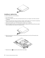
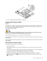
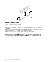
12. Lift the main bracket up a little bit so that the LCD panel detaches from the main bracket, and you can gently pull out the microprocessor fan assembly cable connectors through the hole in the main bracket. 13. Lift the microprocessor fan assembly and cables up and out of the main bracket. Installing a microprocessor fan assembly To install a microprocessor fan assembly, do the following: 1. Reinstall the four screws that attach the new microprocessor fan assembly to the main bracket. 2. Lift the main bracket up so that you can route the microprocessor fan assembly cables through the hole in the main bracket. Connect the microprocessor fan assembly cables to the system board connectors. Chapter 8. Replacing FRUs 83
-
 1
1 -
2
-
3
-
4
-
5
-
6
-
7
-
8
-
9
-
10
-
11
-
12
-
13
-
14
-
15
-
16
-
17
-
18
-
19
-
20
-
21
-
22
-
23
-
24
-
25
-
26
-
27
-
28
-
29
-
30
-
31
-
32
-
33
-
34
-
35
-
36
-
37
-
38
-
39
-
40
-
41
-
42
-
43
-
44
-
45
-
46
-
47
-
48
-
49
-
50
-
51
-
52
-
53
-
54
-
55
-
56
-
57
-
58
-
59
-
60
-
61
-
62
-
63
-
64
-
65
-
66
-
67
-
68
-
69
-
70
-
71
-
72
-
73
-
74
-
75
-
76
-
77
-
78
-
79
-
80
-
81
-
82
-
83
-
 84
84 -
 85
85 -
 86
86 -
 87
87 -
 88
88 -
 89
89 -
 90
90 -
 91
91 -
 92
92 -
 93
93 -
 94
94 -
95
-
96
-
97
-
98
-
99
-
100
-
101
-
102
-
103
-
104
-
105
-
106
-
107
-
108
-
109
-
110
-
111
-
112
-
113
-
114
-
115
-
116
-
117
-
118
-
119
-
120
-
121
-
122
-
123
-
124
-
125
-
126
-
127
-
128
-
129
-
130
-
131
-
132
-
133
-
134
-
135
-
136
-
137
-
138
-
139
-
140
-
141
-
142
-
143
-
144
-
145
-
146
-
147
-
148
-
149
-
150
-
151
-
152
-
153
-
154
-
155
-
156
-
157
-
158
-
159
-
160
-
161
-
162
-
163
-
164
-
165
-
166
-
167
-
168
-
169
-
170
-
171
-
172
-
173
-
174
-
175
-
176
-
177
-
178
-
179
-
180
-
181
-
182
-
183
-
184
-
185
-
186
-
187
-
188
-
189
-
190
-
191
-
192
-
193
-
194
 |
 |

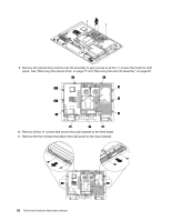
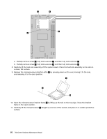
12. Lift the main bracket up a little bit so that the LCD panel detaches from the main bracket, and you can
gently pull out the microprocessor fan assembly cable connectors through the hole in the main bracket.
13. Lift the microprocessor fan assembly and cables up and out of the main bracket.
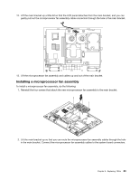
Installing a microprocessor fan assembly
To install a microprocessor fan assembly, do the following:
1. Reinstall the four screws that attach the new microprocessor fan assembly to the main bracket.
2. Lift the main bracket up so that you can route the microprocessor fan assembly cables through the hole
in the main bracket. Connect the microprocessor fan assembly cables to the system board connectors.
Chapter 8
.
Replacing FRUs
83