Lenovo ThinkCentre A70z Hardware Maintenance Manual for ThinkCentre A70z - Page 87
Replacing the microprocessor fan assembly, Removing the microprocessor fan assembly - fan repair
 |
View all Lenovo ThinkCentre A70z manuals
Add to My Manuals
Save this manual to your list of manuals |
Page 87 highlights
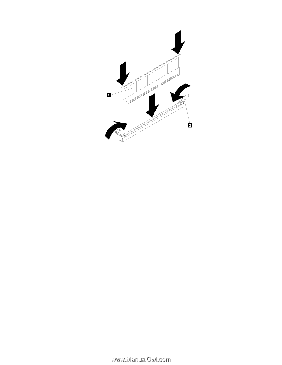
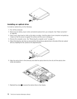
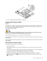
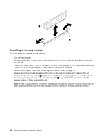
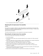
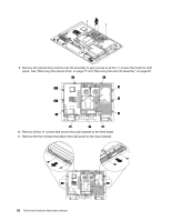
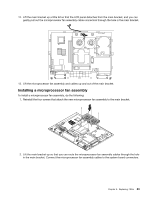
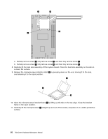
7. Go to "Completing the FRU installation" on page 108. Replacing the microprocessor fan assembly Attention Do not open your computer or attempt any repair before reading and understanding the "Important safety information" in the ThinkCentre Safety and Warranty Guide that came with your computer. To obtain a copy of the ThinkCentre Safety and Warranty Guide, go to: http://www.lenovo.com/support This section provides instructions on how to replace the microprocessor fan assembly. Removing the microprocessor fan assembly To remove the microprocessor fan assembly, do the following: 1. Turn off the computer. 2. Disconnect all cables, power cords, and external options from your computer. See "Rear connectors" on page 65. 3. Place a soft, clean towel or cloth on the desk or surface. Hold the sides of your computer and gently lay it down so that the screen is against the surface and the cover is facing up. 4. Remove the computer cover. See "Removing the computer cover" on page 70. 5. Open the system board shielding. See "Opening the system board shielding" on page 71. 6. Disconnect the microprocessor fan assembly cables from the system board. See "System board connectors" on page 68. 7. Remove the heat sink assembly to gain access to the microprocessor fan assembly. See "Removing the microprocessor and heat sink assembly" on page 85. 8. Remove the four screws that attach the microprocessor fan assembly to the main bracket. Chapter 8. Replacing FRUs 81
-
 1
1 -
2
-
3
-
4
-
5
-
6
-
7
-
8
-
9
-
10
-
11
-
12
-
13
-
14
-
15
-
16
-
17
-
18
-
19
-
20
-
21
-
22
-
23
-
24
-
25
-
26
-
27
-
28
-
29
-
30
-
31
-
32
-
33
-
34
-
35
-
36
-
37
-
38
-
39
-
40
-
41
-
42
-
43
-
44
-
45
-
46
-
47
-
48
-
49
-
50
-
51
-
52
-
53
-
54
-
55
-
56
-
57
-
58
-
59
-
60
-
61
-
62
-
63
-
64
-
65
-
66
-
67
-
68
-
69
-
70
-
71
-
72
-
73
-
74
-
75
-
76
-
77
-
78
-
79
-
80
-
81
-
 82
82 -
 83
83 -
 84
84 -
 85
85 -
 86
86 -
 87
87 -
 88
88 -
 89
89 -
 90
90 -
 91
91 -
 92
92 -
93
-
94
-
95
-
96
-
97
-
98
-
99
-
100
-
101
-
102
-
103
-
104
-
105
-
106
-
107
-
108
-
109
-
110
-
111
-
112
-
113
-
114
-
115
-
116
-
117
-
118
-
119
-
120
-
121
-
122
-
123
-
124
-
125
-
126
-
127
-
128
-
129
-
130
-
131
-
132
-
133
-
134
-
135
-
136
-
137
-
138
-
139
-
140
-
141
-
142
-
143
-
144
-
145
-
146
-
147
-
148
-
149
-
150
-
151
-
152
-
153
-
154
-
155
-
156
-
157
-
158
-
159
-
160
-
161
-
162
-
163
-
164
-
165
-
166
-
167
-
168
-
169
-
170
-
171
-
172
-
173
-
174
-
175
-
176
-
177
-
178
-
179
-
180
-
181
-
182
-
183
-
184
-
185
-
186
-
187
-
188
-
189
-
190
-
191
-
192
-
193
-
194
 |
 |