Lenovo ThinkCentre A70z Hardware Maintenance Manual for ThinkCentre A70z - Page 111
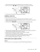
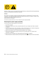
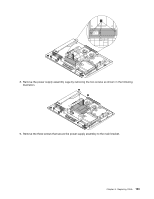
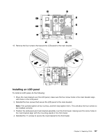
that secure the power connector bracket to the main bracket.
 |
View all Lenovo ThinkCentre A70z manuals
Add to My Manuals
Save this manual to your list of manuals |
Page 111 highlights
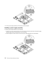
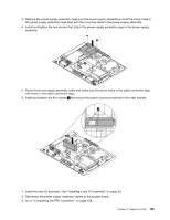
3. Replace the power supply assembly cage over the power supply assembly so that the screw holes in the power supply assembly cage align with the mounting studs in the power supply assembly. 4. Install and tighten the two screws that attach the power supply assembly cage to the power supply assembly. 5. Route the power supply assembly cable and make sure the screw holes in the cable connector align with those in the cable connector cage. 6. Install and tighten the five screws 1 that secure the power connector bracket to the main bracket. 7. Install the rear I/O assembly. See "Installing a rear I/O assembly" on page 93. 8. Reconnect the power supply assembly cables to the system board. 9. Go to "Completing the FRU installation" on page 108. Chapter 8. Replacing FRUs 105
-
 1
1 -
2
-
3
-
4
-
5
-
6
-
7
-
8
-
9
-
10
-
11
-
12
-
13
-
14
-
15
-
16
-
17
-
18
-
19
-
20
-
21
-
22
-
23
-
24
-
25
-
26
-
27
-
28
-
29
-
30
-
31
-
32
-
33
-
34
-
35
-
36
-
37
-
38
-
39
-
40
-
41
-
42
-
43
-
44
-
45
-
46
-
47
-
48
-
49
-
50
-
51
-
52
-
53
-
54
-
55
-
56
-
57
-
58
-
59
-
60
-
61
-
62
-
63
-
64
-
65
-
66
-
67
-
68
-
69
-
70
-
71
-
72
-
73
-
74
-
75
-
76
-
77
-
78
-
79
-
80
-
81
-
82
-
83
-
84
-
85
-
86
-
87
-
88
-
89
-
90
-
91
-
92
-
93
-
94
-
95
-
96
-
97
-
98
-
99
-
100
-
101
-
102
-
103
-
104
-
105
-
 106
106 -
 107
107 -
 108
108 -
 109
109 -
 110
110 -
 111
111 -
 112
112 -
 113
113 -
 114
114 -
 115
115 -
 116
116 -
117
-
118
-
119
-
120
-
121
-
122
-
123
-
124
-
125
-
126
-
127
-
128
-
129
-
130
-
131
-
132
-
133
-
134
-
135
-
136
-
137
-
138
-
139
-
140
-
141
-
142
-
143
-
144
-
145
-
146
-
147
-
148
-
149
-
150
-
151
-
152
-
153
-
154
-
155
-
156
-
157
-
158
-
159
-
160
-
161
-
162
-
163
-
164
-
165
-
166
-
167
-
168
-
169
-
170
-
171
-
172
-
173
-
174
-
175
-
176
-
177
-
178
-
179
-
180
-
181
-
182
-
183
-
184
-
185
-
186
-
187
-
188
-
189
-
190
-
191
-
192
-
193
-
194
 |
 |
