Lenovo ThinkCentre A70z Hardware Maintenance Manual for ThinkCentre A70z - Page 107
Installing a system fan, Replacing the power supply assembly
 |
View all Lenovo ThinkCentre A70z manuals
Add to My Manuals
Save this manual to your list of manuals |
Page 107 highlights
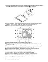
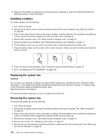
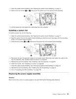
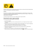
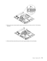
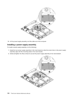
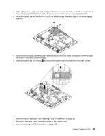
7. Open the system board shielding. See "Opening the system board shielding" on page 71. 8. Remove the two screws, 1 and 2 , that secure the system fan to the system board shielding. 9. Lift the system fan and system fan cable away from the computer. Installing a system fan To install a system fan, do the following: 1. Open the system board shielding. See "Opening the system board shielding" on page 71. 2. Align the system fan over the system board shielding so that the screw holes align with the mounting studs in the system board shielding. 3. Install the two screws, 1 and 2 , that secure the system fan to the system board shielding. 4. Reconnect the rear I/O assembly cables to the system board. Reconnect the system fan cable to the rear I/O assembly. See "System board connectors" on page 68. 5. Reinstall the rear I/O assembly. See "Installing a rear I/O assembly" on page 93. 6. Install the inverter. See "Installing an inverter" on page 98. 7. Close the system board shielding. See "Closing the system board shielding" on page 72. 8. Reinstall the rear I/O shielding. See "Installing the rear I/O shielding" on page 74. 9. Go to "Completing the FRU installation" on page 108. Replacing the power supply assembly Attention Never remove the cover on a power supply or any part that has the following label attached. Chapter 8. Replacing FRUs 101
-
 1
1 -
2
-
3
-
4
-
5
-
6
-
7
-
8
-
9
-
10
-
11
-
12
-
13
-
14
-
15
-
16
-
17
-
18
-
19
-
20
-
21
-
22
-
23
-
24
-
25
-
26
-
27
-
28
-
29
-
30
-
31
-
32
-
33
-
34
-
35
-
36
-
37
-
38
-
39
-
40
-
41
-
42
-
43
-
44
-
45
-
46
-
47
-
48
-
49
-
50
-
51
-
52
-
53
-
54
-
55
-
56
-
57
-
58
-
59
-
60
-
61
-
62
-
63
-
64
-
65
-
66
-
67
-
68
-
69
-
70
-
71
-
72
-
73
-
74
-
75
-
76
-
77
-
78
-
79
-
80
-
81
-
82
-
83
-
84
-
85
-
86
-
87
-
88
-
89
-
90
-
91
-
92
-
93
-
94
-
95
-
96
-
97
-
98
-
99
-
100
-
101
-
 102
102 -
 103
103 -
 104
104 -
 105
105 -
 106
106 -
 107
107 -
 108
108 -
 109
109 -
 110
110 -
 111
111 -
 112
112 -
113
-
114
-
115
-
116
-
117
-
118
-
119
-
120
-
121
-
122
-
123
-
124
-
125
-
126
-
127
-
128
-
129
-
130
-
131
-
132
-
133
-
134
-
135
-
136
-
137
-
138
-
139
-
140
-
141
-
142
-
143
-
144
-
145
-
146
-
147
-
148
-
149
-
150
-
151
-
152
-
153
-
154
-
155
-
156
-
157
-
158
-
159
-
160
-
161
-
162
-
163
-
164
-
165
-
166
-
167
-
168
-
169
-
170
-
171
-
172
-
173
-
174
-
175
-
176
-
177
-
178
-
179
-
180
-
181
-
182
-
183
-
184
-
185
-
186
-
187
-
188
-
189
-
190
-
191
-
192
-
193
-
194
 |
 |
