Lenovo ThinkPad X1 Hardware Maintenance Manual - Page 67
Keyboard, When installing, Removal steps of keyboard
 |
View all Lenovo ThinkPad X1 manuals
Add to My Manuals
Save this manual to your list of manuals |
Page 67 highlights
When installing: Make sure that the hard disk drive rubber rails or solid state drive spacers are attached firmly. 1020 Keyboard For access, disable the battery pack first. Refer to "1000 Disabling the battery pack in the UEFI BIOS" on page 58 for detailed instructions. Removal steps of keyboard 1 1 Step 1 Screw (quantity) M2 x 5 mm (2) Color Black Torque 0.181 Nm (1.85 kgfcm) Slightly press the keyboard and slide it a little bit forward, in the direction shown by the arrow 2 , to detach the front edge of the keyboard from the frame. Then, lift up the keyboard in the direction shown by the arrow 3 . 3 2 2 2 Lift the keyboard in the direction shown by the arrow 4 , and then detach the connectors. Chapter 8. Removing and replacing a FRU 61
-
 1
1 -
2
-
3
-
4
-
5
-
6
-
7
-
8
-
9
-
10
-
11
-
12
-
13
-
14
-
15
-
16
-
17
-
18
-
19
-
20
-
21
-
22
-
23
-
24
-
25
-
26
-
27
-
28
-
29
-
30
-
31
-
32
-
33
-
34
-
35
-
36
-
37
-
38
-
39
-
40
-
41
-
42
-
43
-
44
-
45
-
46
-
47
-
48
-
49
-
50
-
51
-
52
-
53
-
54
-
55
-
56
-
57
-
58
-
59
-
60
-
61
-
 62
62 -
 63
63 -
 64
64 -
 65
65 -
 66
66 -
 67
67 -
 68
68 -
 69
69 -
 70
70 -
 71
71 -
 72
72 -
73
-
74
-
75
-
76
-
77
-
78
-
79
-
80
-
81
-
82
-
83
-
84
-
85
-
86
-
87
-
88
-
89
-
90
-
91
-
92
-
93
-
94
-
95
-
96
-
97
-
98
-
99
-
100
-
101
-
102
-
103
-
104
-
105
-
106
-
107
-
108
-
109
-
110
-
111
-
112
-
113
-
114
-
115
-
116
-
117
-
118
-
119
-
120
-
121
-
122
-
123
-
124
-
125
-
126
 |
 |

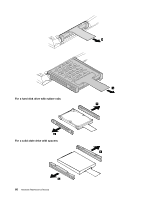
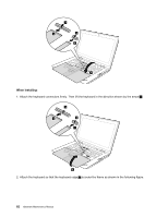
When installing:
Make sure that the hard disk drive rubber rails or solid state drive spacers are attached firmly.
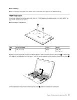
1020 Keyboard
For access, disable the battery pack first. Refer to “1000 Disabling the battery pack in the UEFI BIOS” on
page 58 for detailed instructions.
Removal steps of keyboard
1
1
Step
Screw (quantity)
Color
Torque
1
M2 x 5 mm (2)
Black
0.181 Nm
(1.85 kgfcm)
Slightly press the keyboard and slide it a little bit forward, in the direction shown by the arrow
2
, to detach the
front edge of the keyboard from the frame. Then, lift up the keyboard in the direction shown by the arrow
3
.
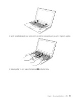
2
2
2
3
Lift the keyboard in the direction shown by the arrow
4
, and then detach the connectors.
Chapter 8
.
Removing and replacing a FRU
61