Lenovo ThinkServer RD330 Hardware Maintenance Manual - ThinkServer RD330 - Page 33
Intelligent Diagnostics Module, Front USB connector 1, Front VGA DB-15 connector - memory
 |
View all Lenovo ThinkServer RD330 manuals
Add to My Manuals
Save this manual to your list of manuals |
Page 33 highlights
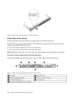
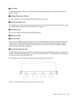
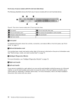
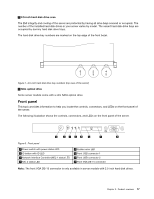
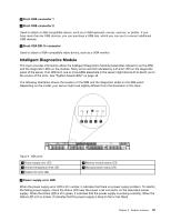
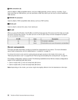
6 Front USB connector 1 7 Front USB connector 2 Used to attach a USB-compatible device, such as a USB keyboard, mouse, scanner, or printer. If you have more than six USB devices, you can purchase a USB hub, which you can use to connect additional USB devices. 8 Front VGA DB-15 connector Used to attach a VGA-compatible video device, such as a VGA monitor. Intelligent Diagnostics Module This topic provides information about the Intelligent Diagnostics Module (hereinafter referred to as the IDM) and the diagnostic LEDs on the module. Many errors are first indicated by a lit error LED on the diagnostic panel of the server. If an LED is lit, one or more LEDs elsewhere in the server might also be lit to direct you to the source of the error. See "System board LEDs" on page 40. The following illustration shows the location of the IDM and the diagnostic LEDs on the IDM panel. Depending on the model, your server might look slightly different from the illustration in this topic. PSU Mem CPU ID PSU Mem CPU Figure 9. IDM panel 1 Power supply error LED 2 Ambient temperature limit LED 3 System fan error LED 4 Memory module status LED 5 Microprocessor status LED 1 Power supply error LED When the power supply error LED is lit in amber, it indicates that there is a power supply problem. To identify the failing power supply, check the status LED near the power cord connector on the redundant power supply. When the status LED is lit in green, it indicates that the power supply is working correctly. When the status LED is lit in amber, it indicates that the power supply is likely to fail or has failed. Chapter 3. Product overview 19
-
 1
1 -
2
-
3
-
4
-
5
-
6
-
7
-
8
-
9
-
10
-
11
-
12
-
13
-
14
-
15
-
16
-
17
-
18
-
19
-
20
-
21
-
22
-
23
-
24
-
25
-
26
-
27
-
 28
28 -
 29
29 -
 30
30 -
 31
31 -
 32
32 -
 33
33 -
 34
34 -
 35
35 -
 36
36 -
 37
37 -
 38
38 -
39
-
40
-
41
-
42
-
43
-
44
-
45
-
46
-
47
-
48
-
49
-
50
-
51
-
52
-
53
-
54
-
55
-
56
-
57
-
58
-
59
-
60
-
61
-
62
-
63
-
64
-
65
-
66
-
67
-
68
-
69
-
70
-
71
-
72
-
73
-
74
-
75
-
76
-
77
-
78
-
79
-
80
-
81
-
82
-
83
-
84
-
85
-
86
-
87
-
88
-
89
-
90
-
91
-
92
-
93
-
94
-
95
-
96
-
97
-
98
-
99
-
100
-
101
-
102
-
103
-
104
-
105
-
106
-
107
-
108
-
109
-
110
-
111
-
112
-
113
-
114
-
115
-
116
-
117
-
118
-
119
-
120
-
121
-
122
-
123
-
124
-
125
-
126
-
127
-
128
-
129
-
130
-
131
-
132
-
133
-
134
-
135
-
136
-
137
-
138
-
139
-
140
-
141
-
142
-
143
-
144
-
145
-
146
-
147
-
148
-
149
-
150
-
151
-
152
-
153
-
154
-
155
-
156
-
157
-
158
-
159
-
160
-
161
-
162
-
163
-
164
-
165
-
166
-
167
-
168
-
169
-
170
-
171
-
172
-
173
-
174
-
175
-
176
-
177
-
178
-
179
-
180
-
181
-
182
-
183
-
184
-
185
-
186
-
187
-
188
-
189
-
190
-
191
-
192
-
193
-
194
-
195
-
196
 |
 |
