Lenovo ThinkServer RD330 Hardware Maintenance Manual - ThinkServer RD330 - Page 47
Intelligent Diagnostics Module connector, Front VGA connector
 |
View all Lenovo ThinkServer RD330 manuals
Add to My Manuals
Save this manual to your list of manuals |
Page 47 highlights
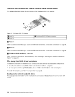
5 Front VGA connector 6 SATA connector 0 7 SAS connector 4-7 8 SAS connector 0-3 9 System board battery 10 Platform Controller Hub (PCH) 11 Internal USB Type A connector 1 12 TMM Premium connector 13 Internal USB Type A connector 2 14 TPM connector 15 iButton socket 16 ThinkServer Management Module 21 Backplane power connector 1 22 Backplane power connector 2 23 System fan 7 connector 24 Microprocessor socket 2 25 System fan 6 connector 26 Memory slots (6) 27 System fan 5 connector 28 System fan 3 connector 29 Microprocessor socket 1 30 System fan 2 connector 31 Memory slots (6) 32 System fan 1 connector 1 Front panel connector Used to connect the front panel cable. 2 Internal USB connector 1 Used to connect the front panel USB cable. 3 Internal USB connector 2 Reserved for the manufacturer. 4 Intelligent Diagnostics Module connector Used to connect the cable of the Intelligent Diagnostics Module. 5 Front VGA connector Used to connect the cable of the front VGA connector on the front panel of the server. 6 SATA connector 0 Used to connect the signal cable of the slim optical drive if the server has one installed. 7 SAS connector 4-7 Used to connect the mini-SAS connector on one end of a mini-SAS to mini-SAS signal cable to support the hard disk drive 4 to hard disk drive 5. 8 SAS connector 0-3 Used to connect the mini-SAS connector on one end of a mini-SAS to mini-SAS signal cable to support the hard disk drive 0 to hard disk drive 3. Chapter 3. Product overview 33
-
 1
1 -
2
-
3
-
4
-
5
-
6
-
7
-
8
-
9
-
10
-
11
-
12
-
13
-
14
-
15
-
16
-
17
-
18
-
19
-
20
-
21
-
22
-
23
-
24
-
25
-
26
-
27
-
28
-
29
-
30
-
31
-
32
-
33
-
34
-
35
-
36
-
37
-
38
-
39
-
40
-
41
-
 42
42 -
 43
43 -
 44
44 -
 45
45 -
 46
46 -
 47
47 -
 48
48 -
 49
49 -
 50
50 -
 51
51 -
 52
52 -
53
-
54
-
55
-
56
-
57
-
58
-
59
-
60
-
61
-
62
-
63
-
64
-
65
-
66
-
67
-
68
-
69
-
70
-
71
-
72
-
73
-
74
-
75
-
76
-
77
-
78
-
79
-
80
-
81
-
82
-
83
-
84
-
85
-
86
-
87
-
88
-
89
-
90
-
91
-
92
-
93
-
94
-
95
-
96
-
97
-
98
-
99
-
100
-
101
-
102
-
103
-
104
-
105
-
106
-
107
-
108
-
109
-
110
-
111
-
112
-
113
-
114
-
115
-
116
-
117
-
118
-
119
-
120
-
121
-
122
-
123
-
124
-
125
-
126
-
127
-
128
-
129
-
130
-
131
-
132
-
133
-
134
-
135
-
136
-
137
-
138
-
139
-
140
-
141
-
142
-
143
-
144
-
145
-
146
-
147
-
148
-
149
-
150
-
151
-
152
-
153
-
154
-
155
-
156
-
157
-
158
-
159
-
160
-
161
-
162
-
163
-
164
-
165
-
166
-
167
-
168
-
169
-
170
-
171
-
172
-
173
-
174
-
175
-
176
-
177
-
178
-
179
-
180
-
181
-
182
-
183
-
184
-
185
-
186
-
187
-
188
-
189
-
190
-
191
-
192
-
193
-
194
-
195
-
196
 |
 |
