Lenovo ThinkServer RD330 Hardware Maintenance Manual - ThinkServer RD330 - Page 36
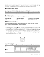
Server components, USB connectors 4, VGA DB-15 connector, Serial port, ID LED
 |
View all Lenovo ThinkServer RD330 manuals
Add to My Manuals
Save this manual to your list of manuals |
Page 36 highlights
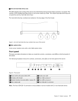
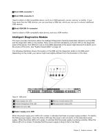
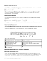
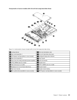
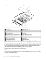
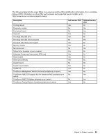
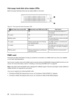
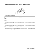
6 USB connectors (4) Used to attach a USB-compatible device, such as a USB keyboard, mouse, scanner, or printer. If you have more than six USB devices, you can purchase a USB hub, which you can use to connect additional USB devices. 7 VGA DB-15 connector Used to attach a VGA-compatible video device, such as a VGA monitor. 10 Serial port Used to attach a device that uses a 9-pin serial port. 11 ID LED When you press the ID button, the ID LEDs on both the front and rear of the server are lit to help you locate the server among other servers. You also can turn on the ID LEDs using a remote management program for server presence detection. ID LED On Off Color Blue None Description The server is identified. The ID LED is not in use or the server is not identified. Server components This topic provides information to help you locate the components of your server. For more information about major components, see the related topics in "Locations" on page 13. To remove the server cover and the cooling shroud and gain access to the inside of the server, see "Removing the server cover" on page 69 and "Removing and reinstalling the cooling shroud" on page 73. The chassis configuration varies by model. The following illustrations show the two chassis configurations based on the supported hard disk drives. • Server models with 3.5-inch hot-swap hard disk drives • Server models with 2.5-inch hot-swap hard disk drives Note: Depending on the model, your server might look slightly different from the illustrations in this topic. 22 ThinkServer RD330 Hardware Maintenance Manual
-
 1
1 -
2
-
3
-
4
-
5
-
6
-
7
-
8
-
9
-
10
-
11
-
12
-
13
-
14
-
15
-
16
-
17
-
18
-
19
-
20
-
21
-
22
-
23
-
24
-
25
-
26
-
27
-
28
-
29
-
30
-
 31
31 -
 32
32 -
 33
33 -
 34
34 -
 35
35 -
 36
36 -
 37
37 -
 38
38 -
 39
39 -
 40
40 -
 41
41 -
42
-
43
-
44
-
45
-
46
-
47
-
48
-
49
-
50
-
51
-
52
-
53
-
54
-
55
-
56
-
57
-
58
-
59
-
60
-
61
-
62
-
63
-
64
-
65
-
66
-
67
-
68
-
69
-
70
-
71
-
72
-
73
-
74
-
75
-
76
-
77
-
78
-
79
-
80
-
81
-
82
-
83
-
84
-
85
-
86
-
87
-
88
-
89
-
90
-
91
-
92
-
93
-
94
-
95
-
96
-
97
-
98
-
99
-
100
-
101
-
102
-
103
-
104
-
105
-
106
-
107
-
108
-
109
-
110
-
111
-
112
-
113
-
114
-
115
-
116
-
117
-
118
-
119
-
120
-
121
-
122
-
123
-
124
-
125
-
126
-
127
-
128
-
129
-
130
-
131
-
132
-
133
-
134
-
135
-
136
-
137
-
138
-
139
-
140
-
141
-
142
-
143
-
144
-
145
-
146
-
147
-
148
-
149
-
150
-
151
-
152
-
153
-
154
-
155
-
156
-
157
-
158
-
159
-
160
-
161
-
162
-
163
-
164
-
165
-
166
-
167
-
168
-
169
-
170
-
171
-
172
-
173
-
174
-
175
-
176
-
177
-
178
-
179
-
180
-
181
-
182
-
183
-
184
-
185
-
186
-
187
-
188
-
189
-
190
-
191
-
192
-
193
-
194
-
195
-
196
 |
 |
