Netgear FVS318N FVS318 Reference Manual - Page 76
LAN A, Set up the two LANs to have different IP address ranges. - setup port forwarding
 |
View all Netgear FVS318N manuals
Add to My Manuals
Save this manual to your list of manuals |
Page 76 highlights
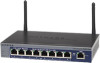
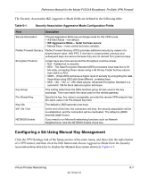
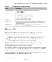
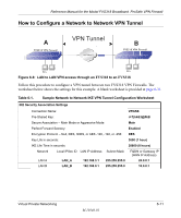
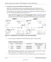
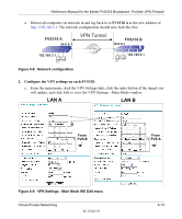
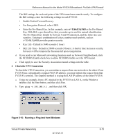
Reference Manual for the Model FVS318 Broadband ProSafe VPN Firewall 1. Set up the two LANs to have different IP address ranges. Note: The LAN IP address ranges of each connected network must be different. The connection will fail if both are using the NETGEAR default address range of 192.168.0.x. This procedure uses the settings in the configuration worksheet above. A blank worksheet you can use to record your settings is provided on page 6-31. a. Log in to the FVS318 on LAN A at its default LAN address of http://192.168.0.1 with its default user name of admin and password of password. Click the LAN IP Setup link in the main menu Advanced section to display the LAN TCP/IP Setup menu shown below. LAN A LAN B Figure 6-7: Configuring the Local LAN (A) via the LAN IP Setup Menu b. For this example, configure the FVS318 settings on LANs A and B as follows: Network Configuration Settings Network LAN IP Address LAN A LAN B 192.168.3.1 192.168.0.1 Subnet Mask 255.255.255.0 255.255.255.0 FQDN or Gateway IP (WAN IP Address) 24.0.0.1 10.0.0.1 Note: If port forwarding, trusted user, or static routes are set up, you will need to change these configurations to match the 192.168.3.x network as well. c. Click Apply. Because you changed the Firewall's IP address, you are now disconnected. 6-12 M-10146-01 Virtual Private Networking
-
 1
1 -
2
-
3
-
4
-
5
-
6
-
7
-
8
-
9
-
10
-
11
-
12
-
13
-
14
-
15
-
16
-
17
-
18
-
19
-
20
-
21
-
22
-
23
-
24
-
25
-
26
-
27
-
28
-
29
-
30
-
31
-
32
-
33
-
34
-
35
-
36
-
37
-
38
-
39
-
40
-
41
-
42
-
43
-
44
-
45
-
46
-
47
-
48
-
49
-
50
-
51
-
52
-
53
-
54
-
55
-
56
-
57
-
58
-
59
-
60
-
61
-
62
-
63
-
64
-
65
-
66
-
67
-
68
-
69
-
70
-
 71
71 -
 72
72 -
 73
73 -
 74
74 -
 75
75 -
 76
76 -
 77
77 -
 78
78 -
 79
79 -
 80
80 -
 81
81 -
82
-
83
-
84
-
85
-
86
-
87
-
88
-
89
-
90
-
91
-
92
-
93
-
94
-
95
-
96
-
97
-
98
-
99
-
100
-
101
-
102
-
103
-
104
-
105
-
106
-
107
-
108
-
109
-
110
-
111
-
112
-
113
-
114
-
115
-
116
-
117
-
118
-
119
-
120
-
121
-
122
-
123
-
124
-
125
-
126
-
127
-
128
-
129
-
130
-
131
-
132
-
133
-
134
-
135
-
136
-
137
-
138
-
139
-
140
-
141
-
142
-
143
-
144
-
145
-
146
-
147
-
148
-
149
-
150
-
151
-
152
-
153
-
154
-
155
-
156
-
157
-
158
-
159
-
160
-
161
-
162
-
163
-
164
-
165
-
166
-
167
-
168
-
169
-
170
-
171
-
172
-
173
-
174
-
175
-
176
-
177
-
178
-
179
-
180
-
181
-
182
-
183
-
184
-
185
-
186
-
187
-
188
-
189
-
190
-
191
-
192
-
193
-
194
-
195
-
196
-
197
-
198
-
199
-
200
-
201
-
202
-
203
-
204
-
205
-
206
-
207
-
208
-
209
-
210
-
211
-
212
-
213
-
214
-
215
-
216
-
217
-
218
-
219
-
220
-
221
-
222
 |
 |