Oki OF5800 Service Guide - Page 215
Open the Printer Cover.
 |
View all Oki OF5800 manuals
Add to My Manuals
Save this manual to your list of manuals |
Page 215 highlights
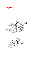
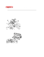
Service Manual for OF5800 Chapter 5 Disassembly Page: 187 1. Remove the scanner assy. 2. Remove the middle frame. 3. Open the Printer Cover. 4. Remove the two rear PCB cover mounting screws and remove the rear PCB cover. 5. Remove the five rear frame mounting screws and remove the rear frame. 6. Remove the printer I/F PCB mounting screw, disconnect the two connectors, and remove the printer I/F PCB. 7. Remove the three printer mechanical controller pcb mounting screws, disconnect the twelve connectors and remove the mechanical controller.
-
 1
1 -
2
-
3
-
4
-
5
-
6
-
7
-
8
-
9
-
10
-
11
-
12
-
13
-
14
-
15
-
16
-
17
-
18
-
19
-
20
-
21
-
22
-
23
-
24
-
25
-
26
-
27
-
28
-
29
-
30
-
31
-
32
-
33
-
34
-
35
-
36
-
37
-
38
-
39
-
40
-
41
-
42
-
43
-
44
-
45
-
46
-
47
-
48
-
49
-
50
-
51
-
52
-
53
-
54
-
55
-
56
-
57
-
58
-
59
-
60
-
61
-
62
-
63
-
64
-
65
-
66
-
67
-
68
-
69
-
70
-
71
-
72
-
73
-
74
-
75
-
76
-
77
-
78
-
79
-
80
-
81
-
82
-
83
-
84
-
85
-
86
-
87
-
88
-
89
-
90
-
91
-
92
-
93
-
94
-
95
-
96
-
97
-
98
-
99
-
100
-
101
-
102
-
103
-
104
-
105
-
106
-
107
-
108
-
109
-
110
-
111
-
112
-
113
-
114
-
115
-
116
-
117
-
118
-
119
-
120
-
121
-
122
-
123
-
124
-
125
-
126
-
127
-
128
-
129
-
130
-
131
-
132
-
133
-
134
-
135
-
136
-
137
-
138
-
139
-
140
-
141
-
142
-
143
-
144
-
145
-
146
-
147
-
148
-
149
-
150
-
151
-
152
-
153
-
154
-
155
-
156
-
157
-
158
-
159
-
160
-
161
-
162
-
163
-
164
-
165
-
166
-
167
-
168
-
169
-
170
-
171
-
172
-
173
-
174
-
175
-
176
-
177
-
178
-
179
-
180
-
181
-
182
-
183
-
184
-
185
-
186
-
187
-
188
-
189
-
190
-
191
-
192
-
193
-
194
-
195
-
196
-
197
-
198
-
199
-
200
-
201
-
202
-
203
-
204
-
205
-
206
-
207
-
208
-
209
-
 210
210 -
 211
211 -
 212
212 -
 213
213 -
 214
214 -
 215
215 -
 216
216 -
 217
217 -
 218
218 -
 219
219 -
 220
220 -
221
-
222
-
223
-
224
-
225
-
226
-
227
-
228
-
229
-
230
-
231
-
232
-
233
-
234
-
235
-
236
-
237
-
238
-
239
-
240
-
241
-
242
-
243
-
244
-
245
-
246
-
247
-
248
-
249
-
250
-
251
-
252
-
253
-
254
-
255
-
256
-
257
-
258
-
259
-
260
-
261
-
262
-
263
-
264
-
265
-
266
-
267
-
268
-
269
-
270
-
271
-
272
-
273
-
274
 |
 |

Page: 187
Service Manual for OF5800
Chapter 5 Disassembly
1. Remove the scanner assy.
2. Remove the middle frame.
3. Open the Printer Cover.
4. Remove the two rear PCB cover mounting screws and remove the rear PCB cover.
5. Remove the five rear frame mounting screws and remove the rear frame.
6. Remove the printer I/F PCB mounting screw, disconnect the two connectors, and remove the printer
I/F PCB.
7. Remove the three printer mechanical controller pcb mounting screws, disconnect the twelve
connectors and remove the mechanical controller.