Oki OKIPOS 407II ParallelBlack Users Guide - Page 43
Black mark specifications
 |
View all Oki OKIPOS 407II ParallelBlack manuals
Add to My Manuals
Save this manual to your list of manuals |
Page 43 highlights
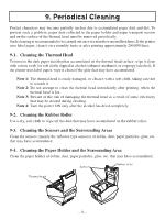
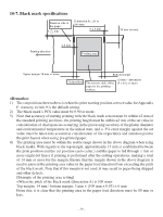
10-7. Black mark specifications Reverse side of the paper 1 +1 -0.8 mm Dimension A = 30 to 300 mm 5 ± 1 mm Printing direction 2.5 mm Printing area 15 mm or more Upper margin 14 mm or more Bottom margin Cut position The reverse side of the paper is the printing surface. (3 mm + dimension A × 3%) or more 1) The cut position shown above is when the print starting position correct value for Appendix F: memory switch 9 is the default setting. 2) The black mark's PCS value must be 0.90 or more. 3) Note that accuracy of starting printing with the black mark sensor must be within ±2 mm of the standard printing positions, the printing length must be within ±2 mm of the set value in consideration of discrepancies occurring in the processing accuracy of the platen diameter and environmental temperature in the initial state, and a -5% error margin against the set value must be taken into account in consideration of life expectancy and attention paid to the print layout when using pre-printed paper. 4) The printing area must be within the usable range shown in the above diagram when using black marks. With regards to the top margin, approximately 13 mm is established between the print position and the cut position (auto cutter,) and the paper is fed through 1 mm or more (eight dot lines) if printing is performed after the cutting operations, making a total of 14 mm or more for the margin. Ensure that the margin shown in the above diagram is used to prevent the printing area value in the paper feed direction from exceeding the pitch of the black mark. Note that if this margin is not used, it may result in pages being skipped and other defects. [Example of the printing area setting] Top margin: 14 mm / bottom margin: 3 mm + (100 mm × 0.03) = 6 mm From this, it is clear that the printing area in the paper feed direction must be 80 mm or less. - 39 -
-
 1
1 -
2
-
3
-
4
-
5
-
6
-
7
-
8
-
9
-
10
-
11
-
12
-
13
-
14
-
15
-
16
-
17
-
18
-
19
-
20
-
21
-
22
-
23
-
24
-
25
-
26
-
27
-
28
-
29
-
30
-
31
-
32
-
33
-
34
-
35
-
36
-
37
-
 38
38 -
 39
39 -
 40
40 -
 41
41 -
 42
42 -
 43
43 -
 44
44 -
 45
45 -
 46
46 -
 47
47 -
 48
48 -
49
-
50
-
51
-
52
-
53
-
54
-
55
-
56
-
57
-
58
-
59
-
60
-
61
-
62
-
63
-
64
-
65
 |
 |
