Oki OKIPOS 407II ParallelBlack Users Guide - Page 63
Minimum resistance for coils L1 and L2 is 24 Ω., Average Rectified Current Io = 1
 |
View all Oki OKIPOS 407II ParallelBlack manuals
Add to My Manuals
Save this manual to your list of manuals |
Page 63 highlights
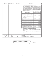
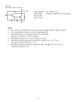
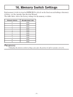
Reference 2SD 1866 Circuit Configuration Drive Output: 24 V, Max. 1.0 A TR1, TR2: Transistor 2SD 1866 or equivalent R1=10 kW R2=33 kW Note: 1. Pin 1 must be shield drain wire connected to peripheral device frame ground. 2. It is not possible to drive two drives simultaneously. 3. The peripheral drive duty must satisfy the following: ON time / (ON time + OFF time) 0.2 4. Minimum resistance for coils L1 and L2 is 24 Ω. 5. Absolute maximum ratings for diodes D1 and D2 (Ta = 25 °C) are: Average Rectified Current Io = 1 A 6. Absolute maximum rating for transistors TR1 and TR2 (Ta = 25 °C) are: Collector current Ic = 2 A - 59 -
-
 1
1 -
2
-
3
-
4
-
5
-
6
-
7
-
8
-
9
-
10
-
11
-
12
-
13
-
14
-
15
-
16
-
17
-
18
-
19
-
20
-
21
-
22
-
23
-
24
-
25
-
26
-
27
-
28
-
29
-
30
-
31
-
32
-
33
-
34
-
35
-
36
-
37
-
38
-
39
-
40
-
41
-
42
-
43
-
44
-
45
-
46
-
47
-
48
-
49
-
50
-
51
-
52
-
53
-
54
-
55
-
56
-
57
-
 58
58 -
 59
59 -
 60
60 -
 61
61 -
 62
62 -
 63
63 -
 64
64 -
 65
65
 |
 |

– µ¸ –
Note:
±.
Pin ± must be shield drain wire connected to peripheral device frame ground.
².
It is not possible to drive two drives simultaneously.
³.
The peripheral drive duty must satisfy the following:
ON time / (ON time + OFF time)
0.²
4.
Minimum resistance for coils L1 and L2 is 24 Ω.
µ.
Absolute maximum ratings for diodes D± and D² (Ta = ²µ °C) are:
Average Rectified Current Io = 1 A
6.
Absolute maximum rating for transistors TR± and TR² (Ta = ²µ °C) are:
Collector current Ic = ² A
Drive Output:
²´ V, Max. ±.0 A
TR±, TR²:
Transistor ²SD ±·66 or equivalent
R±=±0 kW
R²=³³ kW
Reference
2SD 1866 Circuit Configuration