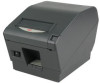
Oki OKIPOS 407II ParallelBlack Users Guide - Page 60
Cable Connections, 4. Electrical Characteristics
 |
View all Oki OKIPOS 407II ParallelBlack manuals
Add to My Manuals
Save this manual to your list of manuals |
Page 60 highlights
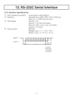
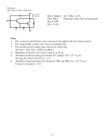
13-3. Cable Connections The followings are a recommended interface cable connections. Printer side Host side 25 pin 9 pin FG 1 TXD 2 RXD 3 RTS 4 CTS 5 DSR 6 SG 7 DTR 20 INIT 25 1 FG 2 3 TXD 3 2 RXD 4 7 RTS 5 8 CTS 6 6 DSR 7 5 SG 8 1 DCD 20 4 DTR Note: Use shielded wire less than 3 m in length. 13-4. Electrical Characteristics Voltage -3 V to -15 V +3 V to +15 V Data signal Mark Space Control signal OFF ON Binary status 1 0 - 56 -
-
 1
1 -
2
-
3
-
4
-
5
-
6
-
7
-
8
-
9
-
10
-
11
-
12
-
13
-
14
-
15
-
16
-
17
-
18
-
19
-
20
-
21
-
22
-
23
-
24
-
25
-
26
-
27
-
28
-
29
-
30
-
31
-
32
-
33
-
34
-
35
-
36
-
37
-
38
-
39
-
40
-
41
-
42
-
43
-
44
-
45
-
46
-
47
-
48
-
49
-
50
-
51
-
52
-
53
-
54
-
 55
55 -
 56
56 -
 57
57 -
 58
58 -
 59
59 -
 60
60 -
 61
61 -
 62
62 -
 63
63 -
 64
64 -
 65
65
 |
 |

– µ6 –
13-3. Cable Connections
The followings are a recommended interface cable connections.
Note:
Use shielded wire less than ³ m in length.
13-4. Electrical Characteristics
Voltage
Data signal
Control signal
Binary status
-³ V to -±µ V
Mark
OFF
±
+³ V to +±µ V
Space
ON
0
1
2
3
4
5
6
1
2
3
4
5
6
7
8
20
FG
FG
TXD
RXD
RTS
CTS
DSR
20
25
7
SG
DTR
INIT
3
2
7
8
6
5
1
4
TXD
RXD
RTS
CTS
DSR
SG
DCD
DTR
Printer side
Host side
25 pin
9 pin