Oki OKIPOS 407II ParallelBlack Users Guide - Page 62
Peripheral Unit Drive Circuit
 |
View all Oki OKIPOS 407II ParallelBlack manuals
Add to My Manuals
Save this manual to your list of manuals |
Page 62 highlights
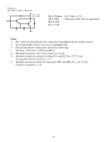
15. Peripheral Unit Drive Circuit Peripheral unit drive circuit connector only connects to peripheral units such as cash drawers, etc. Do not connect it to a telephone. Use cables which meet the following specifications. Peripheral Drive Connector Pin Signal No. name Function I/O direction 1 FG Frame ground - 2 DRD1 Drive signal 1 OUT 3 +24 V Drive power OUT 4 +24 V Drive power OUT 5 DRD2 Drive signal 2 OUT 6 DRSNS Sense signal IN Drive circuit The recommended drive unit is shown below. 1 6 Modular plug Modular plug: MOLEX 90075-0007, AMP641337, or BURNDY B-66-4 Shield Wire lead Separated Ground wire connected to shield (Europe only). Peripheral drive connector 61 6-P Modular jack connector F.G TR1 M-GND +24 V TR2 1 2 D1 7824 3 4 D2 5 M-GND +5 V R1 TR3 6 R2 Printer side - 58 - With shield L1 Peripheral unit R3 4.7 kΩ L2 1/4 W Peripheral unit 2 Frame ground User side Compulsion switch
-
 1
1 -
2
-
3
-
4
-
5
-
6
-
7
-
8
-
9
-
10
-
11
-
12
-
13
-
14
-
15
-
16
-
17
-
18
-
19
-
20
-
21
-
22
-
23
-
24
-
25
-
26
-
27
-
28
-
29
-
30
-
31
-
32
-
33
-
34
-
35
-
36
-
37
-
38
-
39
-
40
-
41
-
42
-
43
-
44
-
45
-
46
-
47
-
48
-
49
-
50
-
51
-
52
-
53
-
54
-
55
-
56
-
 57
57 -
 58
58 -
 59
59 -
 60
60 -
 61
61 -
 62
62 -
 63
63 -
 64
64 -
 65
65
 |
 |
