Panasonic AG DVX100B Dvc Camcorder - Page 44
Switching Audio Input, Using the built-in microphone, Using another microphone and audio equipment, - phantom power to mic
 |
UPC - 791871302231
View all Panasonic AG DVX100B manuals
Add to My Manuals
Save this manual to your list of manuals |
Page 44 highlights
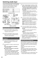
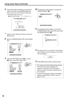
Switching Audio Input You can record audio through two channels when shooting (see the table below). You can switch the source for each channel between the built-in microphone, another microphone, or audio equipment connected to the camera. Built-in microphone L Built-in microphone R INPUT 1 (XLR) INPUT 2 (XLR) CH1 CH2 CH1 CH2 CH2 SELECT switch CH1 SELECT switch INPUT 1/2 (MIC POWER +48V) Switch INPUT 1/2 switches AUDIO control knob Using the built-in microphone 1 Switch the CH1 SELECT switch to INT (L). • Audio from the built-in microphone Lch is recorded to audio channel 1. 2 Switch the CH2 SELECT switch to INT (R). • Audio from the built-in microphone Rch is recorded to audio channel 2. Using another microphone and audio equipment 1 Connect an external microphone or audio equipment to the INPUT 1/2 (XLR 3-pin) terminal. (Page 59) 2 Use the INPUT 1/2 switch to switch the audio input. LINE: (audio equipment is connected) Input level is 0 dBu. MIC: (another microphone is connected) Input level is -50 dBu. You can change the input level to -60 dBu in the setup menus, RECORDING SETUP screen MIC GAIN 1 and MIC GAIN 2 (Page 74). Be aware that sensitivity will be higher if you choose -60 dBu so you will record more noise. 44 3 When using the phantom microphone, set the INPUT 1/2 (MIC POWER +48V) switch to ON. ON: (When using the phantom microphone) 48V power supply to INPUT 1/2 terminal. OFF: (When a phantom microphone is not connected) No power supply for INPUT 1/2 terminal. • The battery will discharge faster if you use a phantom microphone. • Set to OFF if you connect equipment not compatible with +48V. You can damage such equipment if you leave the setting at ON. 4 Use the CH1 SELECT switch to select the input signal to be recorded to audio channel 1. INT (L): Audio from the built-in microphone Lch is recorded to audio channel 1. INPUT 1: Audio from a device connected to INPUT 1 terminal is recorded to channel 1. INPUT 2: Audio from a device connected to INPUT 2 terminal is recorded to channel 1. 5 Use the CH2 SELECT switch to select the input signal to be recorded to audio channel 2. INT (R): Audio from the built-in microphone Rch is recorded to audio channel 2. INPUT 2: Audio from a device connected to INPUT 2 terminal is recorded to channel 2. • When inputting the microphone signal to channels 1 and 2, connect the microphone to INPUT 2 and switch both CH1 SELECT and CH2 SELECT to INPUT 2. Adjusting the recording level Use the AUDIO control knob to adjust the recording level of the built-in microphone or of audio signals input through the INPUT 1/2 (XLR 3-pin) terminal. To adjust the volume of the sound for monitoring (Page 36). Leave it in the center position under normal conditions. Adjust the record level of audio signal using this knob, regardless of the settings of MIC ALC items in the RECORDING SETUP screen of setting menu. (Page 74). • The audio signals input into AUDIO IN/OUT CH1/ CH2 (pin jack) terminals can not be adjusted.
-
 1
1 -
2
-
3
-
4
-
5
-
6
-
7
-
8
-
9
-
10
-
11
-
12
-
13
-
14
-
15
-
16
-
17
-
18
-
19
-
20
-
21
-
22
-
23
-
24
-
25
-
26
-
27
-
28
-
29
-
30
-
31
-
32
-
33
-
34
-
35
-
36
-
37
-
38
-
 39
39 -
 40
40 -
 41
41 -
 42
42 -
 43
43 -
 44
44 -
 45
45 -
 46
46 -
 47
47 -
 48
48 -
 49
49 -
50
-
51
-
52
-
53
-
54
-
55
-
56
-
57
-
58
-
59
-
60
-
61
-
62
-
63
-
64
-
65
-
66
-
67
-
68
-
69
-
70
-
71
-
72
-
73
-
74
-
75
-
76
-
77
-
78
-
79
-
80
-
81
-
82
-
83
-
84
-
85
-
86
-
87
-
88
 |
 |
