Panasonic CYVHD9401U 9" Overhead Monitor - Page 10
continued, Identify All Leads, Connect All Leads, Final Installation, Final Checks - accessories
 |
UPC - 037988757169
View all Panasonic CYVHD9401U manuals
Add to My Manuals
Save this manual to your list of manuals |
Page 10 highlights
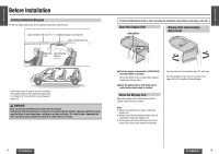
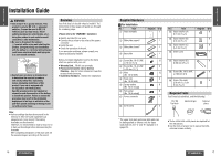
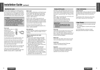
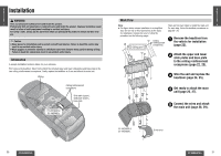
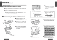
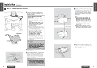
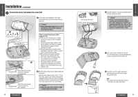
E N Installation Guide (continued) G L I S H Identify All Leads 5 The first step in installation is to identify all the car wires you'll use when hooking up your LCD monitor. As you identify each wire, we suggest that you label it using masking tape and a permanent marker. This will help avoid confusion when making connections later. Caution: ≥ Do not connect the power connector to the unit until the wiring is completed. If there are no plastic caps on the stereo hooking wires, insulate all exposed leads with electrical tape until you are ready to use them. Identify the leads in the following order. Power Lead If your car has a radio or is pre-wired for one: Cut the connector wires one at a time from the plug (leaving the leads as long as possible) so that you can work with individual leads. Turn the ignition on to the accessory position, and ground one lead of the test bulb to the chassis. Touch the other lead of the test bulb to each of the exposed wires from the cut radio connector plug. Touch one wire at a time until you find the outlet that causes the test bulb to light. Now turn the ignition off and then on. If the bulb also turns off and on, that outlet is the car power lead. If your car is not wired for an audio unit: Go to the fuse block and find the fuse port for radio (RADIO), accessory (ACC), or ignition (IGN). Battery Lead If the unit has a yellow lead, you will need to locate the car's battery lead. Otherwise you may ignore this procedure. (The yellow battery lead provides continuous power to maintain a clock, memory storage, or other function.) If your car has a radio or is pre-wired for one: With the ignition and headlights off, identify the car battery lead by grounding one lead of the test bulb to the chassis and checking the remaining exposed wires from the cut radio connector plug. If your car is not wired for an audio unit: Go to the fuse block and find the fuse port for the battery, usually marked BAT. Dome light lead The dome light lead connection varies depending on the type of vehicle. Consult your dealer or service technician. Note for connecting the dome lights (page 30s31): ≥ There are two common types of dome light circuits used, positive or negative switched. Positive systems supply voltage to the interior lights to turn them on, negative switched systems apply ground to illuminate the bulbs. ≥ The dome light lead connection varies depending on the type of vehicle. Consult your dealer or service technician. ≥ Both positive and negative switched light circuits are supported by this unit's door switch. If the door switch is not wired correctly, the dome light will not come on properly. The polarity differs from one model to another so be absolutely sure to ask a dealer or service technician to wire and install the unit. Connect All Leads Now that you have identified all the wires in the car, you are ready to begin connecting them to the LCD monitor wires. The wiring diagram (page 30) shows the proper connections and color coding of the leads. We strongly recommend that you test the unit before making a final installation. You can set the unit on the floor and make temporary connections to test the unit. Use electrical tape to cover all exposed wires. IMPORTANT: ≥ Connect the red power lead last, after you have made and insulated all other connections. Power lead Connect the red power lead to the correct car radio wire or to the appropriate fuse port on the fuse block. If the LCD monitor functions properly with all these connections made, disconnect the wires and proceed to the final installation. Battery lead Connect the yellow battery lead to the correct radio wire or to the battery fuse port on the fuse block. Ground lead Connect the black ground lead of the power connector to the metal car chassis. Equipment Connect any optional equipment according to the instructions furnished with the equipment. Read the operating and installation instructions of any equipment you will connect to this unit. E N G L I Final Installation S H Lead Connections 6 Connect all wires, making sure that each connection is insulated and secure. Bundle all loose wires and fasten them with tape so they will not fall down later. Congratulations! After making a few final checks, you're ready to enjoy your new LCD monitor. Final Checks 1. Make sure that all wires are properly connected and insulated. 2. Turn on the ignition to check the unit for proper operation. If you have difficulties, consult your nearest authorized professional installer for assistance. 18 CY-VHD9401U/L CY-VHD9401U/L 19
-
 1
1 -
2
-
3
-
4
-
 5
5 -
 6
6 -
 7
7 -
 8
8 -
 9
9 -
 10
10 -
 11
11 -
 12
12 -
 13
13 -
 14
14 -
 15
15 -
16
-
17
-
18
-
19
-
20
-
21
-
22
-
23
-
24
-
25
-
26
-
27
-
28
-
29
-
30
-
31
-
32
-
33
-
34
-
35
-
36
-
37
-
38
-
39
-
40
-
41
 |
 |