Panasonic CYVHD9401U 9" Overhead Monitor - Page 17
continued, Wiring Diagram Recommended System - dvd player
 |
UPC - 037988757169
View all Panasonic CYVHD9401U manuals
Add to My Manuals
Save this manual to your list of manuals |
Page 17 highlights
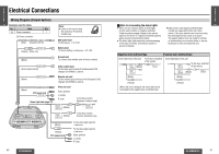
E N Electrical Connections (continued) G L I S H Wiring Diagram (Recommended System) 19 L (white) CY-VHD9401U/CY-VHD9401L R (red) RCA cord (option) VTR(2)-IN Video (yellow) L (white) R (red) REMOTE-OUT (Black) VIDEO-CONT (Green/yellow stripe) RCA cord (option) RCA cord (option) VTR1-IN Video game (option) Video (yellow) L (white) R (red) Example of system combination: ≥ CD player/receiver (CQ-C9801U, option) ≥ DVD changer (CX-DH801U, option) ≥ Video game (option) ≥ VCR, etc. (option) 32 CY-VHD9401U/L REMOTE-IN VIDEO-CONT Video (yellow) L (white) R (red) L (white) E N G L I S H + 20 Front speaker cord FRONT SP - Front speaker + (option) R (red) AUX1-IN Rear speaker cord REAR SP - + - Rear speaker + (option) - CQ-C9801U (option) CX-DH801U (option) or Camcoder (option) or VCR (option) By performing this connection, remote control signals can be received by this unit (CY-VHD9401U/ CY-VHD9401L). (Do not connect the remote control signal receiver supplied with CX-DH801U when this connection has been performed.) Connections: ≥ Connect this unit's (CY-VHD9401U/ CY-VHD9401L) remote-out cord to the REMOTE-IN connector on the DVD changer (CX-DH801U, option) using an RCA cord (option). ≥ Connect this unit's (CY-VHD9401U/ CY-VHD9401L) video control lead to the DVD changer's (CX-DH801U, option) video control lead. ≥ For wiring, carefully read the operating instructions for the devices connected. Remote control unit: ≥The remote control unit supplied with the CX-DH801U must be used to operate the DVD changer (CX-DH801U, option). To use it to perform operations, point it at the remote control signal sensor of this unit (CY-VHD9401U/ CY-VHD9401L). [The DVD changer (CX-DH801U, option) cannot be operated using this unit's (CY-VHD9401U/ CY-VHD9401L) remote control unit.] CY-VHD9401U/L 33
-
 1
1 -
2
-
3
-
4
-
5
-
6
-
7
-
8
-
9
-
10
-
11
-
 12
12 -
 13
13 -
 14
14 -
 15
15 -
 16
16 -
 17
17 -
 18
18 -
 19
19 -
 20
20 -
 21
21 -
 22
22 -
23
-
24
-
25
-
26
-
27
-
28
-
29
-
30
-
31
-
32
-
33
-
34
-
35
-
36
-
37
-
38
-
39
-
40
-
41
 |
 |
