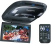
Panasonic CYVHD9401U 9" Overhead Monitor - Page 9
Installation Guide - operating instructions
 |
UPC - 037988757169
View all Panasonic CYVHD9401U manuals
Add to My Manuals
Save this manual to your list of manuals |
Page 9 highlights
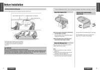
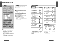
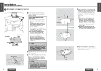
E N Installation Guide G L I S H WARNING: 3 ≥ Use in DC 12 V - ground vehicles. This product is only for DC 12 V - grounded vehicles. It cannot be used in DC 24 V vehicles (such as large trucks, diesel vehicles designed for cold climates, etc.). Using this product in such vehicles could cause fire or other malfunction. ≥ Be sure to disconnect the battery's - terminal while wiring and installing the product. Doing the wiring and installation with the battery's - terminal still connected could cause electrical shock and injury due to a short circuit accidents. ≥ Contact your car dealer or manufacturer to determine the required procedure and strictly follow their instructions before attempting installation of this product if your car is equipped with air bag and/or anti-theft systems. Specific procedures may be required for connection and disconnection of the battery to install this product. Failure to follow the procedure may result in the unintended deployment of air bags or activation of the anti-theft system resulting in damage to the car and personal injury. Note: ≥ Various settings that have been stored in the memory in other on-board equipment (car navigation etc.) may be lost if the battery terminals are disconnected. Therefore, we recommend to make a record of or to back up the settings before disconnecting the terminals. After completing installation of the main unit, set the equipment again according to the record. Overview Your first step is to decide where to install it. The instructions in these pages will guide you through the remaining steps: (Please refer to the "WARNING" statement.) ≥ Identify and label the car wires. ≥ Connect the car wires to the wires of the power connector. ≥ Install the unit. ≥ Check the operation of the unit. If you encounter problems, please consult your nearest professional installer. Before you begin installation, look for the items which are packed with your unit. ≥ Warranty Card... Fill this out promptly. ≥ Panasonic Servicenter List for Service Directory... Keep for future reference in case the product needs servicing. ≥ Installation Hardware... Needed for installation. 16 CY-VHD9401U/L Supplied Hardware ª For Installation No. Item 1 Paper template Diagram Q'ty 1 2 Slide plate (upper)* 1 3 Slide plate (lower)* 1 4 Base plate 1 5 Screw [No. 10-32 UNF, 12 L=10 mm {3/8q}] 6 Screw [No. 10-32 UNF, 6 L=32 mm {11/4q}] 7 Nuts 12 (No. 10-32 UNF) 8 Push nuts 6 (No. 10-32 UNF) 9 Spring washer 6 [No. 10 (5 mm‡)] : Flat washer 6 [No. 10 (5 mm‡)] ; Power connector 1 < Cord clamp 2 No. Item = Space washer (A) [t=1 mm {1/25q}] > Space washer (B) [t=2 mm {2/25q}] ? Space washer (C) [t=3 mm {3/25q}] @ Under cover E N G L I S H 4 Diagram Q'ty 6 6 6 1 A Space washer (D) 6 [t=80 mm {33/16q}] B Screw [No. 10-32 UNF, 6 L=100 mm {4q}] C Screw (for resin) 6 [2.6 mm {1/10q} ‡k 8 mm {8/25q}] Required Tools You'll need a screwdriver, and the following: 12 V DC Test bulb Electrical tape Side-cut pliers * The upper slide plate and lower slide plate can be distinguished as follows: only the upper slide plate has line "A" and "B" stamped on it (page 23). ≥ Tools, cutter knife, cloth pieces are required for the instructions. ≥ Use the tools of proper size to secure the bolts, nuts and screws certainly. CY-VHD9401U/L 17
-
 1
1 -
2
-
3
-
 4
4 -
 5
5 -
 6
6 -
 7
7 -
 8
8 -
 9
9 -
 10
10 -
 11
11 -
 12
12 -
 13
13 -
 14
14 -
15
-
16
-
17
-
18
-
19
-
20
-
21
-
22
-
23
-
24
-
25
-
26
-
27
-
28
-
29
-
30
-
31
-
32
-
33
-
34
-
35
-
36
-
37
-
38
-
39
-
40
-
41
 |
 |
