Panasonic CYVHD9401U 9" Overhead Monitor - Page 12
Installation Procedures
 |
UPC - 037988757169
View all Panasonic CYVHD9401U manuals
Add to My Manuals
Save this manual to your list of manuals |
Page 12 highlights
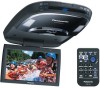
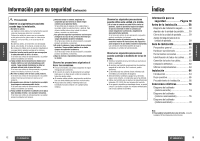
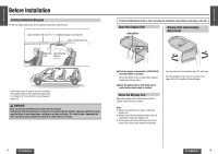
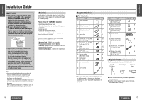
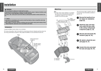
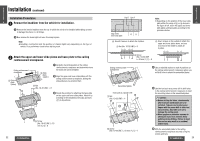
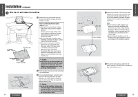
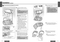
E N Installation (continued) G L I S H Installation Procedures 1 9 Remove the headliner from the vehicle for installation. 1 Remove the interior headliner from the car in which the unit is to be installed while taking care not to damage the interior or its fittings. 2 Now remove the dome light but leave its wiring in place. Note: ≥ Headliner construction and the position of chassis lights vary depending on the type of vehicle. Do a preliminary check before starting work. 2 Attach the upper and lower slide plates and base plate to the ceiling reinforcement crosspieces. Ceiling reinforcement crosspieces 3 Slide plate (lower) 2 Slide plate (upper) 1 Carefully check the position of the ceiling reinforcement crosspieces and determine where the main unit will be installed. 2 Align the upper and lower slide plates with the ceiling reinforcement crosspieces, sliding the slide plates as you position them. 7 Nut (No. 10-32 UNF) a 8 3 Decide the position for attaching the base plate on the upper and lower slide plates. Attach it by screwing in the included screws (5) and nuts (7) in 8 positions. 5 Screw [No. 10-32 UNF, L=10 mm {3/8q}]a 8 22 CY-VHD9401U/L Line B Line A Edge of the lower slide plate B Use all 8 screws to attach the 3 plates. 7 Nut (No. 10-32 UNF)a 8 E N G L I S Note: H ≥ Depending on the position of the lower slide plate within the range of A or B shown in 10 the figure at left, screw the upper and lower slide plates and base plate according to the procedure below. A Use 4 screws on the outside to attach the upper and lower plates alone, and use 4 screws on the inside to attach all 3 plates. 5 Screw [No. 10-32 UNF, L=10 mm {3/8q}] a 8 Ceiling reinforcement crosspieces 4 Use an indelible marker to mark 4 positions on the ceiling reinforcement crosspieces where you will drill holes to attach the assembled plates. Assembled plates Tool such as a power drill 7 Nut (No. 10-32 UNF)a 4 5 5 Screw [No. 10-32 UNF, L=10 mm {3/8q}]a 4 5 Use the tool such as a power drill to drill holes in the ceiling reinforcement crosspieces to meet the mounting holes on the assembled plates. Caution: ≥ Before drilling the holes, check exactly where the unit and bracket are to be installed. Take care not to injure your fingers with the power drill or other tool you are using. Also take care not to damage the ceiling panel. ≥ Wear goggles or protective eyewear to shield your eyes from airborne metal particles during drilling. Failure to heed this caution may result in an accident and/or injury. 6 Affix the assembled plates to the ceiling reinforcement crosspieces securely using the screws and nuts. CY-VHD9401U/L 23
-
 1
1 -
2
-
3
-
4
-
5
-
6
-
 7
7 -
 8
8 -
 9
9 -
 10
10 -
 11
11 -
 12
12 -
 13
13 -
 14
14 -
 15
15 -
 16
16 -
 17
17 -
18
-
19
-
20
-
21
-
22
-
23
-
24
-
25
-
26
-
27
-
28
-
29
-
30
-
31
-
32
-
33
-
34
-
35
-
36
-
37
-
38
-
39
-
40
-
41
 |
 |