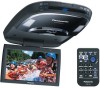
Panasonic CYVHD9401U 9" Overhead Monitor - Page 15

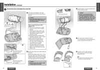
continued, Connect the wires and attach the main unit.

Page 15 highlights

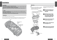
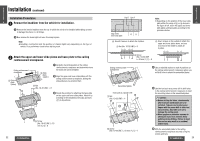
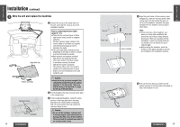
E N Installation (continued) G L I 5 S H Connect the wires and attach the main unit. 15 1 Connect the wires (page 30 to 35) which were pulled out in a previous step to the unit (page 24). 1 See page 30`31. 1 2 Caution: ≥ When connecting stripped wires, be sure to wrap them securely with electrical tape to prevent shorts. Note for connecting the dome lights (page 30s31): ≥ There are two common types of dome light circuits used, positive or negative switched. Positive systems supply voltage to the interior lights to turn them on, negative switched systems apply ground to illuminate the bulbs. ≥ The dome light lead connection varies depending on the type of vehicle. Consult a service technician as needed. ≥ Both positive and negative switched light circuits are supported by this unit's door switch. If the door switch is not wired correctly, the dome light will not come on properly. The polarity differs from one model to another so be absolutely sure to ask a dealer or service technician to wire and install the unit. Where the wires emerge < Cord clamp a 2 in the front seat side (at 2 positions) Where the wires emerge < Cord clamp in the rear seat side a 1 (at 1 position) 2 Bind the wires using the cord clamps (

  • 1
  • 2
  • 3
  • 4
  • 5
  • 6
  • 7
  • 8
  • 9
  • 10
  • 11
  • 12
  • 13
  • 14
  • 15
  • 16
  • 17
  • 18
  • 19
  • 20
  • 21
  • 22
  • 23
  • 24
  • 25
  • 26
  • 27
  • 28
  • 29
  • 30
  • 31
  • 32
  • 33
  • 34
  • 35
  • 36
  • 37
  • 38
  • 39
  • 40
  • 41

28
CY-VHD9401U/L
CY-VHD9401U/L
29
Installation
(continued)
E
N
G
L
I
S
H
15
E
N
G
L
I
S
H
16
3
Insert the bosses of the main unit underside in
the base plate guide holes.
4
Use a screwdriver to tighten the screws
(in 6 positions) that you previously tightened
loosely to secure firmly the main unit.
5
Insert the end of the panel, and push it
back into place as shown in the figure.
Secure the screws.
Note:
Be careful not to scratch the surface of
the front cover when attaching it.
1
Connect the wires (page 30 to 35) which
were pulled out in a previous step to the unit
(page 24).
2
Bind the wires using the cord clamps (
<
) after
connecting.
Caution:
Wires are never to be hit by the screws
or pinched between the plates.
Caution:
When connecting stripped wires, be sure
to wrap them securely with electrical
tape to prevent shorts.
Caution:
If there is any extra wiring, push it
from the pull out opening to behind
the ceiling, taking care so that it is not
pinched between the main unit and base
plate. Failure to heed this caution may
result in an accident and/or injury.
5
Connect the wires and attach the main unit.
1
1
2
Where the wires emerge
in the front seat side
(at 2 positions)
Where the wires emerge
in the rear seat side
(at 1 position)
Push in any extra wire.
<
Cord clamp
a
2
<
Cord clamp
a
1
Bend the cord clamps about 5 mm {
1
/
4
q
} from
their ends, pass the cord clamps through the
installation holes in the main unit’s rear panel,
and then use them to secure the wires. Finally,
cut off the excess parts of the cord clamps.
See page 30
`
31.
Note for connecting the dome lights
(page 30
s
31):
There are two common types of dome
light circuits used, positive or negative
switched.
Positive systems supply voltage to the
interior lights to turn them on, negative
switched systems apply ground to
illuminate the bulbs.
The dome light lead connection varies
depending on the type of vehicle. Consult
a service technician as needed.
Both positive and negative switched
light circuits are supported by this
unit’s door switch. If the door switch
is not wired correctly, the dome
light will not come on properly.
The polarity differs from one model to
another so be absolutely sure to ask a
dealer or service technician to wire and
install the unit.