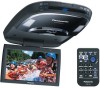
Panasonic CYVHD9401U 9" Overhead Monitor - Page 14
continued, Get ready to attach the main unit. - installation
 |
UPC - 037988757169
View all Panasonic CYVHD9401U manuals
Add to My Manuals
Save this manual to your list of manuals |
Page 14 highlights
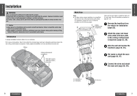
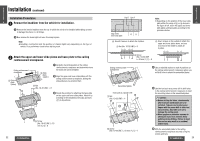
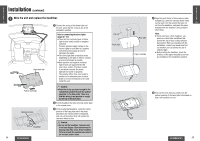
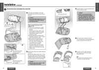
E N Installation (continued) G L I 4 S H Get ready to attach the main unit. 13 1 Open the display unit and remove the 2 screws. Place your fingers at A (in 2 places) on the panel, and slowly pull down the panel. A Front cover AA Note: ≥ Be careful not to scratch the surface of the front cover when removing it. ≥ The screws you remove now will be needed when you re-attach it to complete installation. Keep them in a place where they will not be lost. = or > or ? Space washer* (A or B or C)a6 8 Push nut a 6 2 Insert the screws (6), space washers A, B, or C (=, >, or ?), flat/spring washers (9 and :), and push nuts (8) in the main unit. Keep the screws only loosely tightened until the unit is attached to the base plate. : Flat washer a 6 9 Spring washer a 6 6 Screw a 6 * Depending on the type of vehicle for the installation, you may not need to use some space washers. When the space washers are to be used, make absolutely sure that their height will be the same in all 6 locations. Consult your dealer for details. = or > or ? Space washer* A [t=1 mm {1/25q}] or B [t=2 mm {2/25q}] or C [t=3 mm {3/25q}]a 6 8 Push nut (No. 10-32 UNF) : Flat washer [No. 10 (5 mm‡)] 9 Spring washer 6 Screw [No. 10 (5 mm‡)] [No. 10-32 UNF, L=32 mm {11/4q}] Caution: ≥ Before installing the unit, be absolutely sure to check that the screws do not make any contact with the ceiling panel. If some space is required between the base plate and the unit, attach and adjust the under cover (see next page). For details on installing the under cover, consult your dealer. 26 CY-VHD9401U/L E N G L I ª If some space is required between the base plate and the unit, attach the under cover S H and adjust as follows. 14 8 Push nut (No. 10-32 UNF) 1 Insert the screws (B), space washers D (A), flat/spring washers (9 and :), and push nuts (8) in the main unit and attach the base plate. A Space washer (D) [t=80 mm {33/16q}] Caution: ≥ Before installing the unit, be absolutely sure to check that the screws do not make any contact with the ceiling panel. Main unit : Flat washer [No. 10 (5 mm‡)] 9 Spring washer [No. 10 (5 mm‡)] B Screw [No. 10-32 UNF, L=100 mm {4q}] C Screw [2.6 mm {1/10q} ‡ k 8 mm {8/25q}] a 6 @ Under cover 2 Use the screws (for resin) (C) to attach the accessory under cover (@) to the underside of the main unit. Note: ≥ Depending on the type of vehicle, there may be differences in the gap between the headliner and the main unit. For gaps, adjust the under cover and screw as necessary. CY-VHD9401U/L 27
-
 1
1 -
2
-
3
-
4
-
5
-
6
-
7
-
8
-
 9
9 -
 10
10 -
 11
11 -
 12
12 -
 13
13 -
 14
14 -
 15
15 -
 16
16 -
 17
17 -
 18
18 -
 19
19 -
20
-
21
-
22
-
23
-
24
-
25
-
26
-
27
-
28
-
29
-
30
-
31
-
32
-
33
-
34
-
35
-
36
-
37
-
38
-
39
-
40
-
41
 |
 |
