Pioneer DRM-1004 Operating Instructions - Page 9
Signal
 |
View all Pioneer DRM-1004 manuals
Add to My Manuals
Save this manual to your list of manuals |
Page 9 highlights
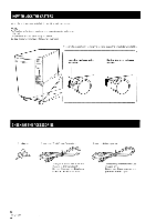
CONNECTIONS Before making or changing the connections, switch off the power switch and disconnect the power cord from the AC outlet. With this unit, each of the drives and Changer mechanism controller is equipped with a special SCSI controller and a couple of external SCSI connectors. This makes it possible to connect them with free SCSI wiring according to the user's operating environment and to control each drive and Changer independently. Equipped with 4 drives IC= Ortv I2'. co= t-g 1 C=IC O'=r ,u.4rf;;K t0o==v ,1^ O ry . ....... e .1,1 e".• - •0 11 \k 20V SeIGNAL 230V Caution in connection: Make sure that the SCSI ID and terminator of each drive have been set properly When daisy chain connection is used, connect the drives and Changer so that the Changer becomes the terminating device, set the terminator SW of each drive to OFF, set that of the Changer to ON, and assign SCSI IDs so that they are not overlapped. NOTE: When setting the SCSI IDs, be careful not to leave the pointer arrow of the SCSI ID switch between two figures; be sure to set the switch so that the arrow points a single figure. When connecting each drive or chain individually to a SCSI controller, set all of the terminator SWs to ON. The changer's SCSI ID switch and the terminator switch are on the back. For the drive, refer to the instruction manual for the drive you are using. Equipped with 4 drives Host computer Drive 1 Drive 2 Drive 3 Drive 4 Changer Term switch OFF OFF OFF OFF ON 9 En
-
 1
1 -
2
-
3
-
 4
4 -
 5
5 -
 6
6 -
 7
7 -
 8
8 -
 9
9 -
 10
10 -
 11
11 -
 12
12 -
 13
13 -
 14
14 -
15
-
16
-
17
-
18
-
19
-
20
-
21
-
22
-
23
-
24
-
25
-
26
-
27
-
28
-
29
-
30
-
31
-
32
-
33
-
34
-
35
-
36
-
37
-
38
-
39
-
40
-
41
-
42
-
43
-
44
-
45
-
46
-
47
-
48
-
49
-
50
-
51
-
52
 |
 |
