Pioneer VSX-55TXi Owner's Manual - Page 36
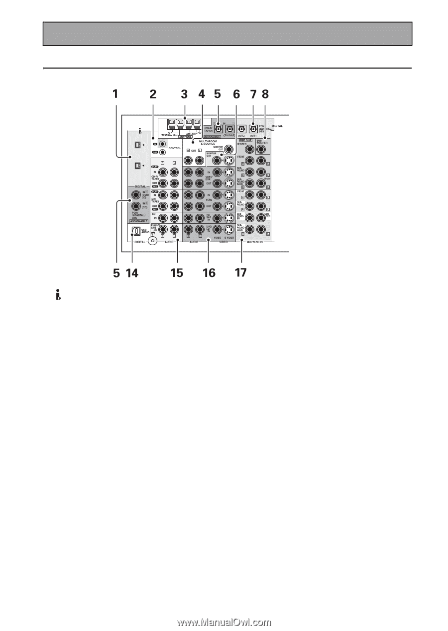
Back Panel
 |
View all Pioneer VSX-55TXi manuals
Add to My Manuals
Save this manual to your list of manuals |
Page 36 highlights
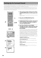
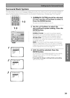
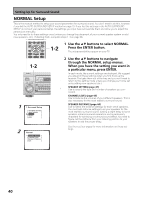
Displays and Controls Back Panel All the terminals on the back panel are explained and/or referenced here. (AUDIO) S400 S400 1 (AUDIO) - i.LINK connectors 4-pin, S400 i.LINK connectors for connection to i.LINK-equipped players and other components. Each i.LINK connector acts simultaneously as both input and output (see page 28). 2 CONTROL IN/OUT terminals (see page 78) You can use these jacks to hook up other PIONEER equipment, that has a CONTROL terminal, so that you can control them all by pointing the remote control(s) at one remote sensor. 3 Radio antenna terminals (see page 24) Hook up antennas for the radio tuner built into the receiver here. 4 MULTI-ROOM & SOURCE OUT terminals (see page 74) These terminals output the audio and video signal to a sub-system in a secondary room. Note that the MONITOR OUT here is different than the MONITOR OUT for the main system. These are analog jacks. 5 36 DIGITAL IN terminals (see page 22) Use these terminals to input the signal from a DVD, CD player or any other kind of digital player. To be able to play Dolby Digital and other surround soundtracks you need to make digital connections. To do this use the digital terminals here. If you don't connect as per the default settings (see page 23) you need to complete "Assigning the Digital Inputs" on page 88. 6 MONITOR OUT terminals (connect a TV or monitor here, see page 16) Use these terminals to output the video signal to your TV, video projector or monitor in your main room. Be careful not to confuse these jacks with the MULTI ROOM & SOURCE MONITOR OUT. 7 DIGITAL OUT terminals (see page 22) Use these terminals to output a digital signal to a DVD-R, CD-R, MD recorder or any other kind of digital recorder. 8 PRE OUT analog terminals (connect an amplifier here, see page 73) Use these terminals to output the audio signal from this amplifier to a different amplifier if that's how you choose to set up your system. 9 COMPONENT VIDEO MONITOR OUT terminals Use these terminals to output the video signal from the COMPONENT VIDEO IN terminals to your TV. See page 16 for more information. 10 12V TRIGGER terminal (see page 95) Use this terminal to output a signal that can automatically turn on another component. DC OUT12V/100mA is the maximum power.
-
 1
1 -
2
-
3
-
4
-
5
-
6
-
7
-
8
-
9
-
10
-
11
-
12
-
13
-
14
-
15
-
16
-
17
-
18
-
19
-
20
-
21
-
22
-
23
-
24
-
25
-
26
-
27
-
28
-
29
-
30
-
 31
31 -
 32
32 -
 33
33 -
 34
34 -
 35
35 -
 36
36 -
 37
37 -
 38
38 -
 39
39 -
 40
40 -
 41
41 -
42
-
43
-
44
-
45
-
46
-
47
-
48
-
49
-
50
-
51
-
52
-
53
-
54
-
55
-
56
-
57
-
58
-
59
-
60
-
61
-
62
-
63
-
64
-
65
-
66
-
67
-
68
-
69
-
70
-
71
-
72
-
73
-
74
-
75
-
76
-
77
-
78
-
79
-
80
-
81
-
82
-
83
-
84
-
85
-
86
-
87
-
88
-
89
-
90
-
91
-
92
-
93
-
94
-
95
-
96
-
97
-
98
-
99
-
100
-
101
-
102
-
103
-
104
-
105
-
106
-
107
-
108
-
109
-
110
-
111
-
112
-
113
-
114
-
115
-
116
-
117
-
118
-
119
 |
 |