Pioneer VSX81TXV Owner's Manual - Page 19
Connecting your equipment, Connecting antennas
 |
UPC - 012562811048
View all Pioneer VSX81TXV manuals
Add to My Manuals
Save this manual to your list of manuals |
Page 19 highlights
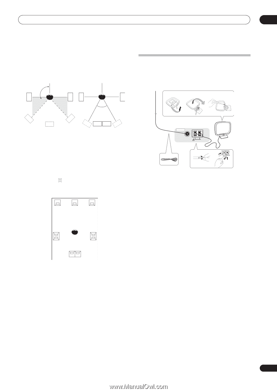
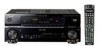
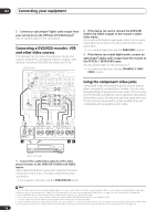
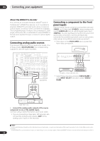
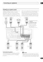
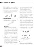
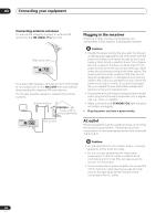
Connecting your equipment 03 The diagrams below show suggested surround and surround back speaker orientation. The first diagram (fig. A) shows orientation with one surround back speaker (or none) connected. The second ( fig. B) shows orientation with two surround back speakers connected. 90º to 120º SL SR SL SR Connecting antennas Connect the AM loop antenna and the FM wire antenna as shown below. To improve reception and sound quality, connect external antennas (see Connecting external antennas below). fig. a fig. b fig. c 0º to 60º SL SB fig. A SR SBL SBL SBR SBR fig. B • If you have two surround back speakers THX recommends placing them together and the same distance from your listening position (see below). THX speaker system setup If you have a complete THX speaker system, follow the diagram below to place your speakers. Note that the surround speakers ( indicates bi-polar radiating speakers) should output at an angle parallel to the listener. L C R SL Surround SR Surround SBL SBR Surround back • If you have two surround back speakers THX recommends placing them together and the same distance from your listening position for the following THX modes: THX Select2 CINEMA, THX MUSICMODE and THX GAMES MODE. See also THX Audio Setting on page 45 to make the settings that will give you the best sound experience when using the Home THX modes (on page 27). 3 ANTENNA 5 FM UNBAL 75 Ω AM LOOP 4 1 2 1 Pull off the protective shields of both AM antenna wires. 2 Push open the tabs, then insert one wire fully into each terminal, then release the tabs to secure the AM antenna wires. 3 Fix the AM loop antenna to the attached stand. To fix the stand to the antenna, bend in the direction indicated by the arrow (fig. a) then clip the loop onto the stand (fig. b). • If you plan to mount the AM antenna to a wall or other surface, secure the stand with screws (fig. c) before clipping the loop to the stand. Make sure the reception is clear. 4 Place the AM antenna on a flat surface and in a direction giving the best reception. 5 Connect the FM wire antenna in the same way as the AM loop antenna. For best results, extend the FM antenna fully and fix to a wall or door frame. Don't drape loosely or leave coiled up. 19 En
-
 1
1 -
2
-
3
-
4
-
5
-
6
-
7
-
8
-
9
-
10
-
11
-
12
-
13
-
 14
14 -
 15
15 -
 16
16 -
 17
17 -
 18
18 -
 19
19 -
 20
20 -
 21
21 -
 22
22 -
 23
23 -
 24
24 -
25
-
26
-
27
-
28
-
29
-
30
-
31
-
32
-
33
-
34
-
35
-
36
-
37
-
38
-
39
-
40
-
41
-
42
-
43
-
44
-
45
-
46
-
47
-
48
-
49
-
50
-
51
-
52
-
53
-
54
-
55
-
56
-
57
-
58
-
59
-
60
-
61
-
62
-
63
-
64
-
65
-
66
-
67
-
68
-
69
-
70
-
71
-
72
-
73
-
74
-
75
-
76
-
77
-
78
-
79
-
80
-
81
-
82
-
83
-
84
 |
 |