Ridgid R4010 Owners Manual - Page 22
On/off Switch, Warning, Using The Variable Flow Valve, Locking / Unlocking The Saw Arm
 |
View all Ridgid R4010 manuals
Add to My Manuals
Save this manual to your list of manuals |
Page 22 highlights
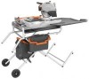
OPERATION on/off SWITCH See Figure 27. This saw is equipped with an on/off switch that has a built-in locking feature. This feature is intended to prevent unauthorized and possible hazardous use by children and others. TO TURN THE SAW ON: Lift the switch to turn ON. TO TURN THE SAW OFF: Press the switch down to turn OFF. To lock THE saw: With the saw turned OFF, install a padlock (not included) through the hole in the switch. On/Off Switch WARNING: In the event of a power failure or when the tool is not in use, turn the switch OFF. This action will prevent the tool from accidentally starting when power returns. WARNING: ALWAYS make sure the workpiece is not in contact with the cutting wheel before operating the switch to start the tool. Failure to heed this warning may cause the workpiece to be kicked back toward the operator and result in serious personal injury. Variable flow valve Warning: To reduce the risk of accidental starting, Always make sure the switch is in the OFF position before plugging tool into the power source. Using the variable flow valve See Figure 28. First turn on the variable flow valve and then the water supply valve. Slowly turn on the spigot from a fresh water main. Watch water flow over the cutting wheel and adjust to desired rate. locking / unlocking the saw arm See Figure 29. To unlock and raise the saw arm: Firmly grasp the "D" handle and apply downward pressure while at the same time turning the lock knob counterclockwise. Slowly raise the saw arm. To lock the saw arm: Firmly grasp the "D" handle and apply downward pressure while at the same time turning the lock knob clockwise to lock. Lock knob 22 - English Switch off Padlock Switch on Fig. 27 Fig. 28 D-handle Fig. 29
-
 1
1 -
2
-
3
-
4
-
5
-
6
-
7
-
8
-
9
-
10
-
11
-
12
-
13
-
14
-
15
-
16
-
 17
17 -
 18
18 -
 19
19 -
 20
20 -
 21
21 -
 22
22 -
 23
23 -
 24
24 -
 25
25 -
 26
26 -
 27
27 -
28
-
29
-
30
-
31
-
32
-
33
-
34
-
35
-
36
-
37
-
38
-
39
-
40
-
41
-
42
-
43
-
44
-
45
-
46
-
47
-
48
-
49
-
50
-
51
-
52
-
53
-
54
-
55
-
56
-
57
-
58
-
59
-
60
-
61
-
62
-
63
-
64
-
65
-
66
-
67
-
68
-
69
-
70
-
71
-
72
-
73
-
74
-
75
-
76
-
77
-
78
-
79
-
80
-
81
-
82
-
83
-
84
-
85
-
86
-
87
-
88
 |
 |
