Sony HDW F900R Operation Manual - Page 124
Connecting Line Input Audio Equipment, IN CH1 or CH2 connector.
 |
View all Sony HDW F900R manuals
Add to My Manuals
Save this manual to your list of manuals |
Page 124 highlights
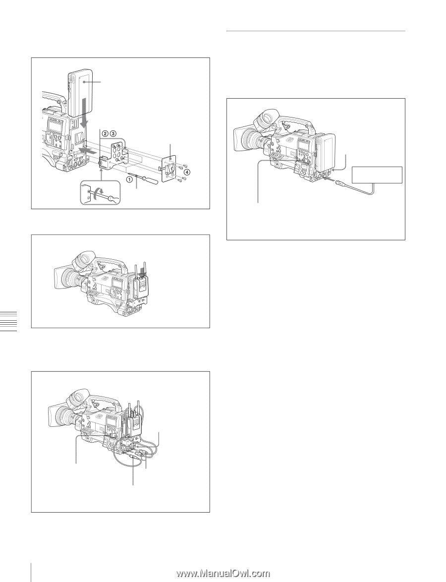
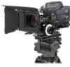
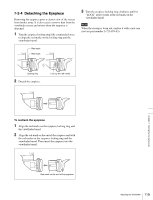
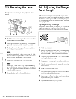
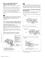
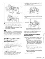
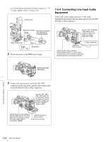
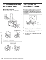
For details about attaching the battery pack, see "7-11 Using a Battery Pack" on page 116. Battery Pack 7-5-4 Connecting Line Input Audio Equipment Connect the audio output connector of the audio equipment that supplies the line input signal to the AUDIO IN CH1 or CH2 connector. Adjustment screws Mount plate (supplied with WRR-861A/ 861B/862A/862B) Back of camcorder Screwdriver 2 Mount the tuner on the WRR tuner fitting. Set the LINE / AES/EBU / MIC switch for the channel to which the audio out cable is attached to LINE. AUDIO IN CH 1 or CH 2 Audio equipment AUDIO IN CH-1/CH-2 switches: Set the AUDIO IN CH-1 or CH-2 switch corresponding to the channel to which the audio equipment is connected to REAR. WRR-861A/861B/ 862A/862B 3 Connect the tuner power cord to the DC OUT connector of the camcorder, and the audio output cable to the AUDIO IN CH1 or CH2 connector. Set the LINE / AES/ EBU / MIC switch for the channel to which the audio out cable is attached to MIC, and set the +48V/OFF switch to OFF. AUDIO IN CH-1/CH-2 switches: Set the AUDIO IN CH-1 or CH-2 switch for the channel to which the audio output cable is connected to REAR. to AUDIO IN CH1 or CH2 connector to DC OUT connector Chapter 7 Setting Up the Camcorder 124 Audio Input System
-
 1
1 -
2
-
3
-
4
-
5
-
6
-
7
-
8
-
9
-
10
-
11
-
12
-
13
-
14
-
15
-
16
-
17
-
18
-
19
-
20
-
21
-
22
-
23
-
24
-
25
-
26
-
27
-
28
-
29
-
30
-
31
-
32
-
33
-
34
-
35
-
36
-
37
-
38
-
39
-
40
-
41
-
42
-
43
-
44
-
45
-
46
-
47
-
48
-
49
-
50
-
51
-
52
-
53
-
54
-
55
-
56
-
57
-
58
-
59
-
60
-
61
-
62
-
63
-
64
-
65
-
66
-
67
-
68
-
69
-
70
-
71
-
72
-
73
-
74
-
75
-
76
-
77
-
78
-
79
-
80
-
81
-
82
-
83
-
84
-
85
-
86
-
87
-
88
-
89
-
90
-
91
-
92
-
93
-
94
-
95
-
96
-
97
-
98
-
99
-
100
-
101
-
102
-
103
-
104
-
105
-
106
-
107
-
108
-
109
-
110
-
111
-
112
-
113
-
114
-
115
-
116
-
117
-
118
-
 119
119 -
 120
120 -
 121
121 -
 122
122 -
 123
123 -
 124
124 -
 125
125 -
 126
126 -
 127
127 -
 128
128 -
 129
129 -
130
-
131
-
132
-
133
-
134
-
135
-
136
-
137
-
138
-
139
-
140
-
141
-
142
-
143
-
144
-
145
-
146
-
147
-
148
-
149
-
150
-
151
-
152
-
153
-
154
-
155
-
156
-
157
-
158
-
159
-
160
-
161
-
162
-
163
-
164
-
165
-
166
-
167
-
168
-
169
-
170
-
171
 |
 |