Sony HDW F900R Operation Manual - Page 52
Checking the Recording on the Color Video Monitor - Playback in Color
 |
View all Sony HDW F900R manuals
Add to My Manuals
Save this manual to your list of manuals |
Page 52 highlights
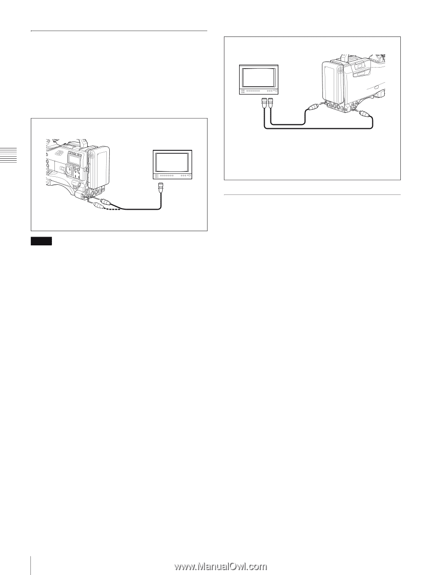
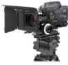
Chapter 3 Recording and Playback 3-3-2 Checking the Recording on the Color Video Monitor - Playback in Color Connect an HD color video monitor with an HD-SDI input connector to the HD-SDI OUT connector of the camcorder. By pressing the PLAY button, you can view the recorded picture. HDW-F900R HD monitor HD-SDI input connector HD-SDI OUT Notes • If HD SDI OUT is set to OFF on the OUTPUT SEL page of the USER menu, you cannot view the recorded picture. Set HD SDI OUT to ON. • When an optional HKDW-702/902R is installed, connect an HD color video monitor to the HD-SDI OUT connector located on the rear of the camcorder. For details, see "5-3-2 Selecting Output Signals" on page 94. When using an optional HKDW-702/902R extension board for down converting Connect the color video monitor to the TEST OUT connector or the HD-SDI OUT connector of the camcorder located on the side of the camcorder. By pressing the PLAY button, you can view the recorded picture. The signal output from each connector depends on the menu settings. For details, see "5-3-2 Selecting Output Signals" on page 94. NTSC/PAL monitor HDW-F900R Video input connector 2) SDI input connector or video input connector 1) HD-SDI OUT 1) TEST OUT 2) 1) For the output signal from the HD-SDI OUT connector, when SDI is selected on the OUTPUT SEL page of the USER menu, connect this connector to the SDI input connector. When VBS is selected, connect it to the video input connector. 2) When SD is selected as the output signal from the TEST OUT connector, connect this connector to the video input connector. 3-3-3 Checking the Camera Picture on the Viewfinder and/or Color Video Monitor Usually, during playback of a tape, if you press the PLAY button, the image sent to the viewfinder, the TEST OUT connector, or the HD-SDI OUT connector is switched back and forth between the camera image and the recorded image. However, the PB VIDEO item on the FUNCTION 2 page of the OPERATION menu allows you to change the setting so that the image seen through the camera is sent to the viewfinder and the TEST OUT connector even while you are playing back a video tape. The HD SDI output from the HD-SDI OUT connector is switched to that of the recorded image during playback, regardless of the PB VIDEO setting. To output recorded video signal to the viewfinder, TEST OUT connector, and the HD-SDI OUT connectors For PB VIDEO (page 142) on the FUNCTION 2 page of the OPERATION menu, set ALL/HDSDI to ALL. To output the recorded video signals to the HDSDI OUT connector, and the camera image to the viewfinder and the TEST OUT connector For PB VIDEO (page 142) on the FUNCTION 2 page of the OPERATION menu, set ALL/HDSDI to HDSDI. 52 Checking Recording and Playback
-
 1
1 -
2
-
3
-
4
-
5
-
6
-
7
-
8
-
9
-
10
-
11
-
12
-
13
-
14
-
15
-
16
-
17
-
18
-
19
-
20
-
21
-
22
-
23
-
24
-
25
-
26
-
27
-
28
-
29
-
30
-
31
-
32
-
33
-
34
-
35
-
36
-
37
-
38
-
39
-
40
-
41
-
42
-
43
-
44
-
45
-
46
-
 47
47 -
 48
48 -
 49
49 -
 50
50 -
 51
51 -
 52
52 -
 53
53 -
 54
54 -
 55
55 -
 56
56 -
 57
57 -
58
-
59
-
60
-
61
-
62
-
63
-
64
-
65
-
66
-
67
-
68
-
69
-
70
-
71
-
72
-
73
-
74
-
75
-
76
-
77
-
78
-
79
-
80
-
81
-
82
-
83
-
84
-
85
-
86
-
87
-
88
-
89
-
90
-
91
-
92
-
93
-
94
-
95
-
96
-
97
-
98
-
99
-
100
-
101
-
102
-
103
-
104
-
105
-
106
-
107
-
108
-
109
-
110
-
111
-
112
-
113
-
114
-
115
-
116
-
117
-
118
-
119
-
120
-
121
-
122
-
123
-
124
-
125
-
126
-
127
-
128
-
129
-
130
-
131
-
132
-
133
-
134
-
135
-
136
-
137
-
138
-
139
-
140
-
141
-
142
-
143
-
144
-
145
-
146
-
147
-
148
-
149
-
150
-
151
-
152
-
153
-
154
-
155
-
156
-
157
-
158
-
159
-
160
-
161
-
162
-
163
-
164
-
165
-
166
-
167
-
168
-
169
-
170
-
171
 |
 |