Sony HDW F900R Operation Manual - Page 25
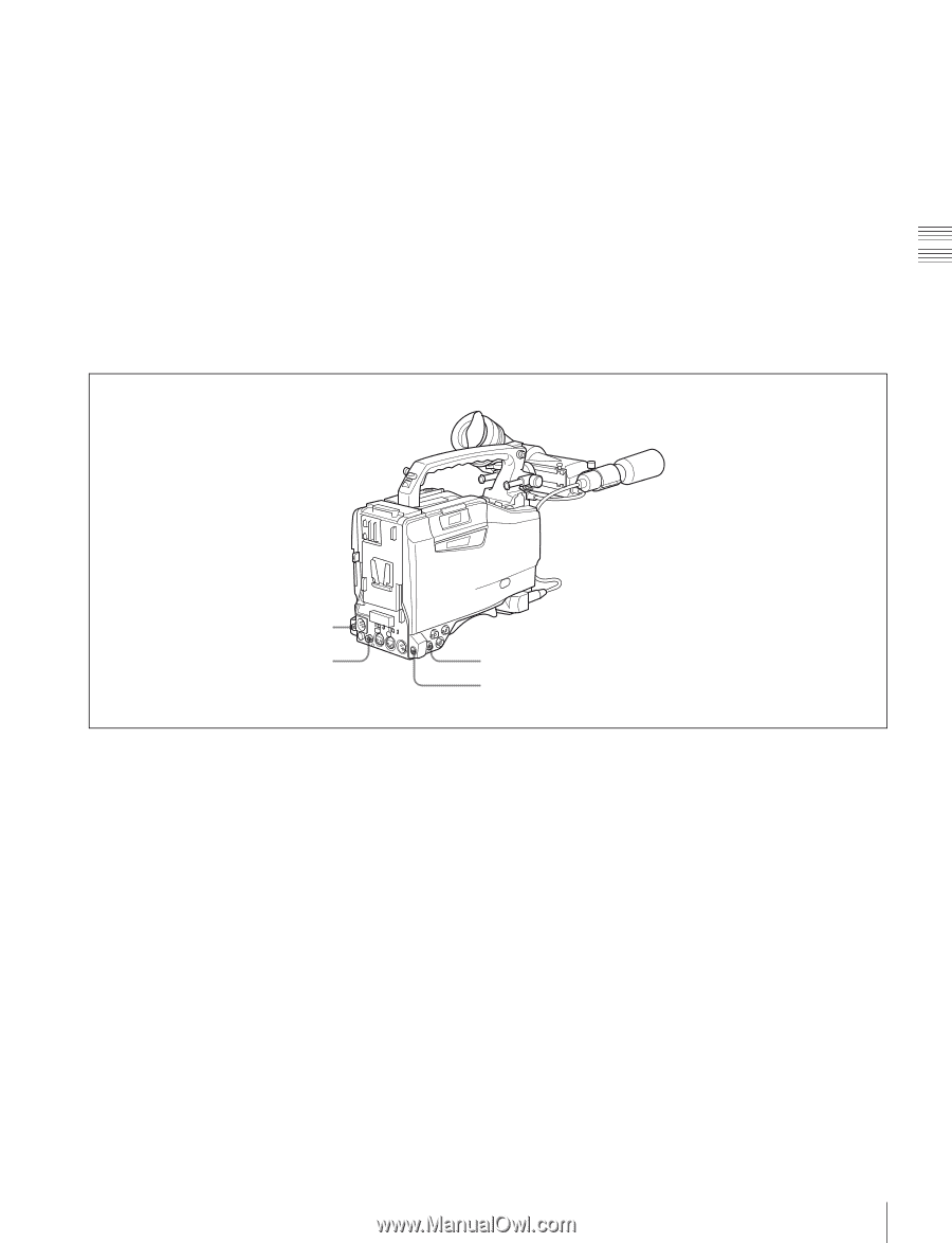
B ATW, TURBO GAIN button, HD-SDI OUT connector BNC type, TEST OUT test output connector BNC type
 |
View all Sony HDW F900R manuals
Add to My Manuals
Save this manual to your list of manuals |
Page 25 highlights
B (ATW): When this switch is set to B and on the FUNCTION 2 page of the OPERATION menu, WHITE SWITCH (page 142) is set to ATW, ATW is activated. When this switch is adjusted, the new setting appears on the setting change/adjustment progress message display area of the viewfinder screen for about 3 seconds. You can assign the ATW ON/OFF function to the ASSIGN 1 switch (push button) on the FUNCTION 1 page of the USER menu. For details, see "5-3-5 Assigning Functions to Assignable Switches" on page 96. u TURBO GAIN button When shooting under extremely poor lighting conditions, press the button once to boost the video gain to the value preset on the GAIN SW page of the USER menu (up to 42 dB). To stop boosting the gain, press the button once more. The gain is reset to the original gain. You can assign the desired function to this TURBO GAIN button like the ASSIGN 1 switch on the FUNCTION 1 page of the USER menu. For details, see "5-3-5 Assigning Functions to Assignable Switches" on page 96. Chapter 2 Locations and Functions of Parts and Controls v HD-SDI OUT connector w HD-SDI OUT connector x TEST OUT connector y REMOTE connector Shooting and recording/playback functions (3) v HD-SDI OUT connector (BNC type) w HD-SDI OUT connector (BNC type) Output an HD-SDI signal for a video monitor. You can select whether or not the signal is output from these connectors using the OUTPUT SEL page of the USER menu. When an optional HKDW-702/902R extension board is attached to the camcorder, the camcorder outputs either a down-converted analog composite signal (color) or an SD SDI signal from the HD-SDI OUT connector located on the side. You can select which signal is output on the OUTPUT SEL page of the USER menu. For details on how to select the output signal, see "5-3-2 Selecting Output Signals" on page 94. converted analog composite signal (color) or an HD-Y signal on the OUTPUT SEL page of the USER menu. For details on how to select the output signal, see "5-3-2 Selecting Output Signals" on page 94. Depending on menu settings, menus, time code, and shot data can be superimposed on the image on the monitor. y REMOTE connector (8-pin) Connect the RM-B150/B750 Remote Control Unit, which makes it possible to control the VTR and camera remotely. x TEST OUT (test output) connector (BNC type) Outputs an HD-Y (standard level, 75-ohm terminated) signal for the video monitor. When an optional HKDW-702/902R extension board is attached to the camcorder, you can select either a down- 25 Shooting and Recording/Playback Functions
-
 1
1 -
2
-
3
-
4
-
5
-
6
-
7
-
8
-
9
-
10
-
11
-
12
-
13
-
14
-
15
-
16
-
17
-
18
-
19
-
 20
20 -
 21
21 -
 22
22 -
 23
23 -
 24
24 -
 25
25 -
 26
26 -
 27
27 -
 28
28 -
 29
29 -
 30
30 -
31
-
32
-
33
-
34
-
35
-
36
-
37
-
38
-
39
-
40
-
41
-
42
-
43
-
44
-
45
-
46
-
47
-
48
-
49
-
50
-
51
-
52
-
53
-
54
-
55
-
56
-
57
-
58
-
59
-
60
-
61
-
62
-
63
-
64
-
65
-
66
-
67
-
68
-
69
-
70
-
71
-
72
-
73
-
74
-
75
-
76
-
77
-
78
-
79
-
80
-
81
-
82
-
83
-
84
-
85
-
86
-
87
-
88
-
89
-
90
-
91
-
92
-
93
-
94
-
95
-
96
-
97
-
98
-
99
-
100
-
101
-
102
-
103
-
104
-
105
-
106
-
107
-
108
-
109
-
110
-
111
-
112
-
113
-
114
-
115
-
116
-
117
-
118
-
119
-
120
-
121
-
122
-
123
-
124
-
125
-
126
-
127
-
128
-
129
-
130
-
131
-
132
-
133
-
134
-
135
-
136
-
137
-
138
-
139
-
140
-
141
-
142
-
143
-
144
-
145
-
146
-
147
-
148
-
149
-
150
-
151
-
152
-
153
-
154
-
155
-
156
-
157
-
158
-
159
-
160
-
161
-
162
-
163
-
164
-
165
-
166
-
167
-
168
-
169
-
170
-
171
 |
 |