Sony HDW F900R Operation Manual - Page 87
Setting Marker Display, Set the MENU ON/OFF switch to ON.
 |
View all Sony HDW F900R manuals
Add to My Manuals
Save this manual to your list of manuals |
Page 87 highlights
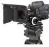
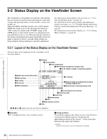
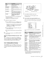
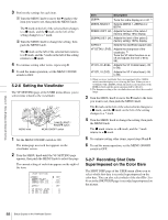
Chapter 5 Menu Displays and Detailed Settings Item 5600K ATW EXTENDER FILTER ND FILTER CC OVERRIDE FORMAT Description 5600K mode ON or OFF ATW ON or OFF Extender ON or OFF ND Types of the ND filter, 1, 2, 3, or 4 CC Types of the CC filter, A, B, C, or D ON or OFF when the reference value of the auto iris adjustment is other than the standard value Frame frequency: 59.94i, 50i, 23.98PsF, 24PsF, 25PsF, or 29.97PsF 1) The SLS mode is effective only when an optional HKDW-905R extension board is installed. 2) Depending on the frame frequency currently selected. For details, see "4-2-1 Shutter Modes" on page 62. 7 Perform the settings for each item. 1 Turn the MENU knob to move the b mark to the item you want to set, then push the MENU knob. The b mark on the left of the selected item changes to a z mark, and the z mark on the left of the setting changes to a ? mark. 2 Turn the MENU knob to change the setting, then push the MENU knob. 3 To continue setting other items, repeat steps 1 and 2. 8 To end the menu operation, set the MENU ON/OFF switch to OFF. When you change the settings only on the '!' LED page The '!' LED page is also registered in the USER menu. You can access this page without opening the TOP page. Open the USER menu by pressing the MENU ON/OFF switch and display this page from the USER menu. 5-2-5 Setting Marker Display The MARKER 1 page of the USER menu allows you to switch the display of the center and safety zone markers on or off and to select the area indicated by the safety zone marker. MENU knob CANCEL/PRST / ESCAPE switch MENU ON/OFF switch 1 Set the MENU ON/OFF switch to ON. The menu page accessed last appears on the viewfinder screen. 2 Turn the MENU knob until the MARKER 1 page appears, then push the MENU knob to select the page. The current setting of each item appears on the right of the item. You can set the following items on the MARKER 1 page. Item MARKER CENTER CENTER MARK SAFETY ZONE SAFETY AREA ASPECT ASPECT SELECT ASPECT MASK1) ASPECT MASK LVL 100% MARKER Description When you do not want to display all markers, set to OFF. To display the center marker, set to ON. Selects the type of center marker (1 to 4), when CENTER is set to ON. To display the safety zone, set to ON. Selects the safety zone range (80%, 90%, 92.5% or 95%), when SAFETY ZONE is set to ON. To display the aspect marker, set to ON. Selects the type (15:9, 14:9, 13:9, 4:3, 1.85, 2.35) of the aspect marker. To make the areas out of the selected aspect marker dimmer, set to ON. Sets the mask level (0 to 8), when the ASPECT MASK is set to ON. To display the effective pixel area, set to ON. 1) The ASPECT MASK item is for processing the signal to be output to the viewfinder. When R, G, or B is selected for the OUTPUT SELECT item from the menu, the masked video signal is output to the TEST OUT connector. 87 Status Display on the Viewfinder Screen
-
 1
1 -
2
-
3
-
4
-
5
-
6
-
7
-
8
-
9
-
10
-
11
-
12
-
13
-
14
-
15
-
16
-
17
-
18
-
19
-
20
-
21
-
22
-
23
-
24
-
25
-
26
-
27
-
28
-
29
-
30
-
31
-
32
-
33
-
34
-
35
-
36
-
37
-
38
-
39
-
40
-
41
-
42
-
43
-
44
-
45
-
46
-
47
-
48
-
49
-
50
-
51
-
52
-
53
-
54
-
55
-
56
-
57
-
58
-
59
-
60
-
61
-
62
-
63
-
64
-
65
-
66
-
67
-
68
-
69
-
70
-
71
-
72
-
73
-
74
-
75
-
76
-
77
-
78
-
79
-
80
-
81
-
 82
82 -
 83
83 -
 84
84 -
 85
85 -
 86
86 -
 87
87 -
 88
88 -
 89
89 -
 90
90 -
 91
91 -
 92
92 -
93
-
94
-
95
-
96
-
97
-
98
-
99
-
100
-
101
-
102
-
103
-
104
-
105
-
106
-
107
-
108
-
109
-
110
-
111
-
112
-
113
-
114
-
115
-
116
-
117
-
118
-
119
-
120
-
121
-
122
-
123
-
124
-
125
-
126
-
127
-
128
-
129
-
130
-
131
-
132
-
133
-
134
-
135
-
136
-
137
-
138
-
139
-
140
-
141
-
142
-
143
-
144
-
145
-
146
-
147
-
148
-
149
-
150
-
151
-
152
-
153
-
154
-
155
-
156
-
157
-
158
-
159
-
160
-
161
-
162
-
163
-
164
-
165
-
166
-
167
-
168
-
169
-
170
-
171
 |
 |