Sony HDW F900R Operation Manual - Page 23
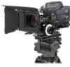
Viewfinder left-right positioning ring, Viewfinder stopper
 |
View all Sony HDW F900R manuals
Add to My Manuals
Save this manual to your list of manuals |
Page 23 highlights
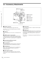
For information about how to change the zebra pattern setting in the setup menu, see "5-2-6 Setting the Viewfinder" on page 88. You can assign the function of the ZEBRA switch to the ASSIGN 1 switch, ASSIGN 2 switch, or TURBO GAIN button on the FUNCTION 1 page of the USER menu. For details, see "5-3-5 Assigning Functions to Assignable Switches" on page 96. g TALLY switch Controls the TALLY indicator, setting its brightness (HIGH or LOW) or turning it off. HIGH: The TALLY indicator brightness is high. OFF: The TALLY indicator is off. LOW: The TALLY indicator brightness is low. h Diopter adjustment ring Adjusts the viewfinder image for your vision. i Viewfinder front-rear positioning lever To adjust the viewfinder position in the front-rear direction, loosen this lever and the LOCK knob. After adjustment, retighten this lever and the LOCK knob. j Viewfinder left-right positioning ring Loosen this ring to move the viewfinder sideways. k Camera operator tally indicator Lights while the camcorder is recording. Slide the window open when you shoot with your eye away from the viewfinder. This indicator flashes when the battery level is running low or the tape is almost full. l Viewfinder stopper Pull up this stopper to detach the viewfinder from the camera. m LOCK knob To adjust the viewfinder position in the front-rear direction, loosen this knob and the viewfinder front-rear positioning lever. After adjustment, retighten this knob and the viewfinder front-rear positioning lever. Chapter 2 Locations and Functions of Parts and Controls n FILTER selector o ASSIGN 1/2 switches p SHUTTER selector q AUTO W/B BAL switch u TURBO GAIN button t WHITE BAL switch s OUTPUT/DCC switch r GAIN selector Shooting and recording/playback functions (2) n FILTER selector Selects the most appropriate filter to match the light source illuminating the subject. When this selector is used with the display mode set to 3, the new setting appears on the viewfinder screen for about 3 seconds. (e.g.: ND: 1, CC: B) The relationships between the selector settings and filter selections as well as examples of filters for different shooting conditions are as follows: FILTER selector (outer knob) setting and CC filter selection FILTER selector (outer knob) setting CC filter selection A 5600K B 3200K C 4300K D 6300K FILTER selector (inner knob) setting and ND filter selection FILTER selector (inner knob) setting ND filter selection 1 Clear 2 1/4 ND 23 Shooting and Recording/Playback Functions
-
 1
1 -
2
-
3
-
4
-
5
-
6
-
7
-
8
-
9
-
10
-
11
-
12
-
13
-
14
-
15
-
16
-
17
-
 18
18 -
 19
19 -
 20
20 -
 21
21 -
 22
22 -
 23
23 -
 24
24 -
 25
25 -
 26
26 -
 27
27 -
 28
28 -
29
-
30
-
31
-
32
-
33
-
34
-
35
-
36
-
37
-
38
-
39
-
40
-
41
-
42
-
43
-
44
-
45
-
46
-
47
-
48
-
49
-
50
-
51
-
52
-
53
-
54
-
55
-
56
-
57
-
58
-
59
-
60
-
61
-
62
-
63
-
64
-
65
-
66
-
67
-
68
-
69
-
70
-
71
-
72
-
73
-
74
-
75
-
76
-
77
-
78
-
79
-
80
-
81
-
82
-
83
-
84
-
85
-
86
-
87
-
88
-
89
-
90
-
91
-
92
-
93
-
94
-
95
-
96
-
97
-
98
-
99
-
100
-
101
-
102
-
103
-
104
-
105
-
106
-
107
-
108
-
109
-
110
-
111
-
112
-
113
-
114
-
115
-
116
-
117
-
118
-
119
-
120
-
121
-
122
-
123
-
124
-
125
-
126
-
127
-
128
-
129
-
130
-
131
-
132
-
133
-
134
-
135
-
136
-
137
-
138
-
139
-
140
-
141
-
142
-
143
-
144
-
145
-
146
-
147
-
148
-
149
-
150
-
151
-
152
-
153
-
154
-
155
-
156
-
157
-
158
-
159
-
160
-
161
-
162
-
163
-
164
-
165
-
166
-
167
-
168
-
169
-
170
-
171
 |
 |
