Sony PDWHR1 User Manual (PDW-HR1 Operation Manual Ed. 1 Rev. 2 for Version 2.0 - Page 28
HDMI output display, No display
 |
View all Sony PDWHR1 manuals
Add to My Manuals
Save this manual to your list of manuals |
Page 28 highlights
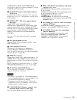
Chapter 2 Names and Functions of Parts 1) The indication and the menu items appear only when the PDBZ-UPG03 Software Upgrade Key or the PDBK-MK1 option board has been installed. h Level bars Display the audio recording or playback levels of channels 1 to 8. The OVER indicators light when the audio level exceeds 0 dB. i Meter display mode Displays the audio level meter display mode selected with AU METER on page P2 AUDIO of the function menu (see page 52). 3 Video information 1 Input signal 2 HDSDI output conversion display 3 Source selection 4 Reference signal 7 HDMI output display 6 SDSDI output conversion display 5 Format conversion display a Input signal Displays the currently selected video input signal. HD-SDI: HDSDI video signal SD-SDI: SDSDI video signal COMPOSITE: Composite video signal (when setup menu item 308 is set to "STD") COMPOSITE(NSTD): Composite video signal (when setup menu item 308 is set to "N-STD") i.LINK: i.LINK TS (HDV) signal 1) DVB-ASI: DVB-ASI TS signal 1) SG: Test video signal generated by the internal signal generator 1)When the PDBK-202 option board is installed Note The display flashes when there is no video input signal, and when the video input signal does not match the system frequency of this unit. Select the video input signal with V INPUT on page P1 VIDEO of the function menu (see page 50). b HDSDI output conversion display When an upconverted or cross converted signal is being supplied to the HDSDI OUTPUT 1 and 2 (SUPER) connectors, displays the formats before and after conversion and the conversion mode. SQ: Squeeze mode EC: Edge-crop mode LB: Letter box mode c Source selection The video monitor displays the video output that is selected with the "SOURCE" sub-item of LCD MODE on the P1 VIDEO page of the function menu. "LCD" appears here in the display area of the selected output. d Reference signal Displays the reference signal to which this unit is synchronized. INPUT: Input video signal HD-REF: HD format reference signal SD-REF: SD format reference signal No display: Internal reference signal Note The HD-REF or SD-REF display flashes if the video input signal is not synchronized with the reference signal, or if the signals are synchronized but out of phase. e Format conversion display When up-conversion or down-conversion is being performed before recording, displays the formats before and after conversion and the conversion mode. SQ: Squeeze mode EC: Edge-crop mode LB: Letter box mode f SDSDI output conversion display When a downconverted signal is being supplied to the SDSDI OUTPUT connector, displays the formats before and after conversion and the conversion mode. SQ: Squeeze mode EC: Edge-crop mode LB: Letter box mode g HDMI output display Displays the signal output to the HDMI OUT connector. 1080i: 1080/59.94i or 1080/50i signal 720P: 720/59.94P or 720/50P signal 480i: 480/59.94i signal 576i: 576/50i signal 480P: 480/59.94P signal 576P: 576/50P signal 28 Display Panel
-
 1
1 -
2
-
3
-
4
-
5
-
6
-
7
-
8
-
9
-
10
-
11
-
12
-
13
-
14
-
15
-
16
-
17
-
18
-
19
-
20
-
21
-
22
-
 23
23 -
 24
24 -
 25
25 -
 26
26 -
 27
27 -
 28
28 -
 29
29 -
 30
30 -
 31
31 -
 32
32 -
 33
33 -
34
-
35
-
36
-
37
-
38
-
39
-
40
-
41
-
42
-
43
-
44
-
45
-
46
-
47
-
48
-
49
-
50
-
51
-
52
-
53
-
54
-
55
-
56
-
57
-
58
-
59
-
60
-
61
-
62
-
63
-
64
-
65
-
66
-
67
-
68
-
69
-
70
-
71
-
72
-
73
-
74
-
75
-
76
-
77
-
78
-
79
-
80
-
81
-
82
-
83
-
84
-
85
-
86
-
87
-
88
-
89
-
90
-
91
-
92
-
93
-
94
-
95
-
96
-
97
-
98
-
99
-
100
-
101
-
102
-
103
-
104
-
105
-
106
-
107
-
108
-
109
-
110
-
111
-
112
-
113
-
114
-
115
-
116
-
117
-
118
-
119
-
120
-
121
-
122
-
123
-
124
-
125
-
126
-
127
-
128
-
129
-
130
-
131
-
132
-
133
-
134
-
135
-
136
-
137
-
138
-
139
-
140
-
141
-
142
-
143
-
144
-
145
-
146
-
147
-
148
-
149
-
150
-
151
-
152
-
153
-
154
-
155
-
156
-
157
-
158
-
159
-
160
-
161
-
162
-
163
-
164
-
165
-
166
-
167
-
168
-
169
-
170
-
171
-
172
-
173
-
174
-
175
-
176
-
177
-
178
-
179
-
180
-
181
-
182
-
183
-
184
-
185
-
186
-
187
-
188
-
189
-
190
-
191
-
192
-
193
-
194
-
195
-
196
-
197
-
198
-
199
 |
 |
