Sony PDWHR1 User Manual (PDW-HR1 Operation Manual Ed. 1 Rev. 2 for Version 2.0 - Page 51
P2 Audio Sub-item, Vec75, Vec100, Black, Input, Setting, Analog1, I.link, Dvb-asi
 |
View all Sony PDWHR1 manuals
Add to My Manuals
Save this manual to your list of manuals |
Page 51 highlights
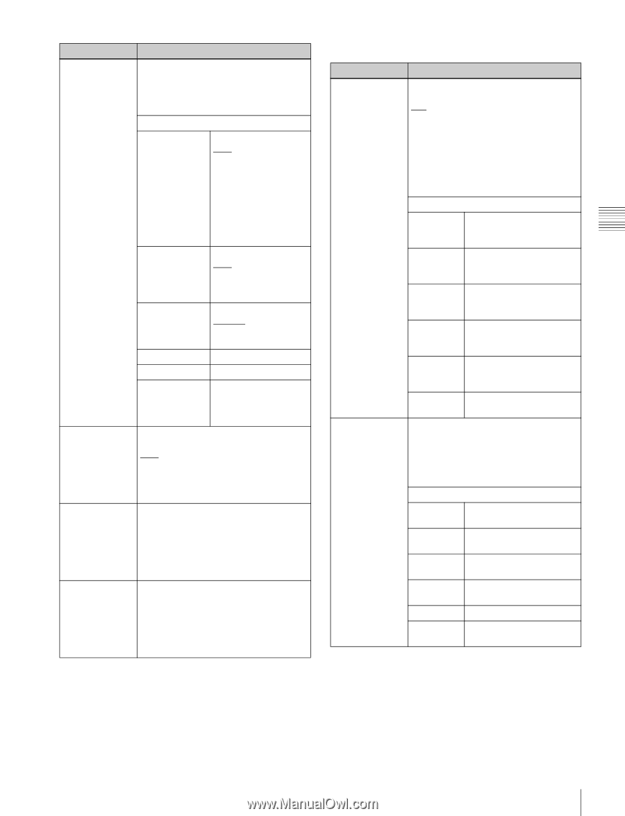
Chapter 3 Preparations Item Setting F3: WFM Makes settings related to display of the waveform monitor or vectorscope. (The waveform monitor or vectorscope appear only when the display is showing the video monitor.) Sub-Item F1: MODE Display mode OFF: Display neither. WFM: Waveform monitor d) VEC75%: 75% color bar signal vectorscope d) VEC100%: 100% color bar signal vectorscope d) F2: POSITION Display position R.B.: Right bottom R.T.: Right top L.T.: Left top L.B.: Left bottom F3: BG Background BLACK: Black (opaque) HALF: Transparent F4: - F5: - F6: EXIT Exits the waveform monitor/vectorscope display settings sub menu. F4: OUT REF Selects the reference signal for the output signals of this unit. REF: Use the signal input to the REF.VIDEO INPUT connector as the output reference signal. INPUT: Use the input video signal as the output reference signal. F5: SYNC Sets the sync phase of HD output signals. While the setting value is flashing, turn the PUSH SET knob to adjust the sync phase of output signals with respect to the input reference signal, over the range ±15 µs. (The display shows -128 to +127.) F6: FINE Makes fine adjustment to the sync phase of HD output signals. While the setting value is flashing, turn the PUSH SET knob to adjust the sync phase of output signals with respect to the input reference signal, over the range ±200 ns. (The display shows 0 to 1023.) a) When V INPUT is set to "SG", "SDI" cannot be selected for AU INPUT on the P2 AUDIO page. b) The settings of setup menu item 950 UP CONVERTER MODE are reflected. c) The settings of setup menu item 930 DOWN CONVERTER MODE are reflected. d) Does not appear when a GUI screen is being displayed. P2 AUDIO page Item F1: AU INPUT F2: REC VOL Setting Selects the audio input signal to assign to audio channels 1 to 8. SDI: Audio signal embedded into SDI signal ANALOG1: Analog 1 audio signal SG: Test signal from internal signal generator i.LINK: i.LINK signal (when the PDBK- 202 option board is installed) DVB-ASI: DVB-ASI signal (when the PDBK-202 option board is installed) Sub-item F1: A1 Input signal of audio INPUT (A5 channel 1 (5) INPUT) F2: A2 Input signal of audio INPUT (A6 channel 2 (6) INPUT) F3: A3 Input signal of audio INPUT (A7 channel 3 (7) INPUT) F4: A4 Input signal of audio INPUT (A8 channel 4 (8) INPUT) F5: A5-A8 (A1-A4) Switches to the sub menu for setting channels 5 to 8 (1 to 4). F6: EXIT Exit the audio input signal selection sub-menu. Sets the recording audio level of audio channels 5 to 8. a) The recording audio level can be adjusted within the range from -200 to +200 (-∞ to +12 dB) by turning the PUSH SET knob. Sub-item F1: A5 VOL Recording audio level of audio channel 5 F2: A6 VOL Recording audio level of audio channel 6 F3: A7 VOL Recording audio level of audio channel 7 F4: A8 VOL Recording audio level of audio channel 8 F5: - F6: EXIT Exit the recording audio level setting sub-menu. 51 Basic Function Menu Operations
-
 1
1 -
2
-
3
-
4
-
5
-
6
-
7
-
8
-
9
-
10
-
11
-
12
-
13
-
14
-
15
-
16
-
17
-
18
-
19
-
20
-
21
-
22
-
23
-
24
-
25
-
26
-
27
-
28
-
29
-
30
-
31
-
32
-
33
-
34
-
35
-
36
-
37
-
38
-
39
-
40
-
41
-
42
-
43
-
44
-
45
-
 46
46 -
 47
47 -
 48
48 -
 49
49 -
 50
50 -
 51
51 -
 52
52 -
 53
53 -
 54
54 -
 55
55 -
 56
56 -
57
-
58
-
59
-
60
-
61
-
62
-
63
-
64
-
65
-
66
-
67
-
68
-
69
-
70
-
71
-
72
-
73
-
74
-
75
-
76
-
77
-
78
-
79
-
80
-
81
-
82
-
83
-
84
-
85
-
86
-
87
-
88
-
89
-
90
-
91
-
92
-
93
-
94
-
95
-
96
-
97
-
98
-
99
-
100
-
101
-
102
-
103
-
104
-
105
-
106
-
107
-
108
-
109
-
110
-
111
-
112
-
113
-
114
-
115
-
116
-
117
-
118
-
119
-
120
-
121
-
122
-
123
-
124
-
125
-
126
-
127
-
128
-
129
-
130
-
131
-
132
-
133
-
134
-
135
-
136
-
137
-
138
-
139
-
140
-
141
-
142
-
143
-
144
-
145
-
146
-
147
-
148
-
149
-
150
-
151
-
152
-
153
-
154
-
155
-
156
-
157
-
158
-
159
-
160
-
161
-
162
-
163
-
164
-
165
-
166
-
167
-
168
-
169
-
170
-
171
-
172
-
173
-
174
-
175
-
176
-
177
-
178
-
179
-
180
-
181
-
182
-
183
-
184
-
185
-
186
-
187
-
188
-
189
-
190
-
191
-
192
-
193
-
194
-
195
-
196
-
197
-
198
-
199
 |
 |