Sony RDR-GX7 Operating Instructions - Page 18
Step 3: Connecting the Video Cords, A Connecting to a video input jack, PB, PR)
 |
View all Sony RDR-GX7 manuals
Add to My Manuals
Save this manual to your list of manuals |
Page 18 highlights
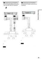
Step 3: Connecting the Video Cords Connect this recorder to your TV monitor, projector, or AV amplifier (receiver) using a video cord. Select one of the following patterns A through C, according to the input jack on your TV monitor, projector, or AV amplifier (receiver). This will enable you to view pictures. Audio connections are explained in "Step 4: Connecting the Audio Cords" (page 19). If you are connecting to a VCR Connect your VCR to the LINE IN (VIDEO) jack on the recorder (page 29). A Connecting to a video input jack Connect the yellow plug of the audio/video cord (supplied) to the yellow (video) jacks. You will enjoy standard quality images. Use the red and white plugs to connect to the audio input jacks (page 20). VHF/UHF IN OUT CONTROL S IN DIGITAL OUT PCM/DTS/DOLBY DIGITAL LINE IN COAXIAL R-AUDIO-L 1 VIDEO S VIDEO LINE OUT R-AUDIO-L VIDEO 1 S VIDEO OPTICAL 3 2 Y PB PR COMPONENT VIDEO OUT DVD recorder ~ AC IN LINE OUT R-AUDIO-L VIDEO 1 S VIDEO 2 to LINE OUT (VIDEO) 1 or 2 (yellow) (yellow) INPUT VIDEO Audio/video cord (supplied) : Signal flow L AUDIO R TV, projector, or AV amplifier (receiver) B Connecting to an S VIDEO input jack Connect using an S VIDEO cord (not supplied). You will enjoy high quality images. VHF/UHF IN OUT CONTROL S IN DIGITAL OUT PCM/DTS/DOLBY DIGITAL LINE IN COAXIAL R-AUDIO-L 1 VIDEO S VIDEO LINE OUT R-AUDIO-L VIDEO 1 S VIDEO OPTICAL 3 2 Y PB PR COMPONENT VIDEO OUT DVD recorder ~ AC IN LINE OUT R-AUDIO-L VIDEO 1 S VIDEO to LINE OUT (S VIDEO) 1 or 2 2 S VIDEO cord (not supplied) INPUT S VIDEO C Connecting to component video input jacks (Y, PB, PR) Connect the component via the COMPONENT VIDEO OUT jacks using a component video cord (not supplied) or three video cords (not supplied) of the same kind and length. You will enjoy accurate color reproduction and high quality images. If your TV accepts progressive (480p) format signals, you must use this connection and then press PROGRESSIVE on the front panel to accept progressive video signals. See "Using the PROGRESSIVE button" (page 51) for more information. VHF/UHF IN OUT CONTROL S IN DVD recorder DIGITAL OUT PCM/DTS/DOLBY DIGITAL LINE IN COAXIAL R-AUDIO-L 1 VIDEO S VIDEO LINE OUT R-AUDIO-L VIDEO 1 S VIDEO OPTICAL 3 2 Y PB PR COMPONENT VIDEO OUT to COMPONENT VIDEO OUT ~ AC IN (green) Y (blue) PB PR (red) (green) (blue) COMPONENT VIDEO IN Y PB PR (red) COMPONENT VIDEO OUT Component video cord (not supplied) TV, projector, or AV amplifier (receiver) : Signal flow When connecting to a standard 4:3 screen TV Depending on the disc, the image may not fit your TV screen. To change the aspect ration, see page 94. If your TV has a CONTROL S jack You can control the recorder by operating the remote toward the TV. This feature is convenient when you placed the recorder and the TV away from each other. After connecting the recorder to other equipment in pattern A, B, or C above, connect the CONTROL S IN jack to your TV's CONTROL S (OUT) jack using a control S cord (not supplied). Refer to the instructions supplied with the TV to be connected. VHF/UHF IN OUT CONTROL S IN DIGITAL OUT PCM/DTS/DOLBY DIGITAL COAXIAL 1 LINE IN R-AUDIO-L VIDEO S VIDEO LINE OUT R-AUDIO-L VIDEO 1 S VIDEO OPTICAL 3 2 DVD recorder Y PB PR COMPONENT VIDEO OUT ~ AC IN CONTROL S IN to CONTROL S IN CONTROL S Control S cord (not supplied) TV : Signal flow : Signal flow TV, projector, or AV amplifier (receiver) 18 Step 3: Connecting the Video Cords
-
 1
1 -
2
-
3
-
4
-
5
-
6
-
7
-
8
-
9
-
10
-
11
-
12
-
 13
13 -
 14
14 -
 15
15 -
 16
16 -
 17
17 -
 18
18 -
 19
19 -
 20
20 -
 21
21 -
 22
22 -
 23
23 -
24
-
25
-
26
-
27
-
28
-
29
-
30
-
31
-
32
-
33
-
34
-
35
-
36
-
37
-
38
-
39
-
40
-
41
-
42
-
43
-
44
-
45
-
46
-
47
-
48
-
49
-
50
-
51
-
52
-
53
-
54
-
55
-
56
-
57
-
58
-
59
-
60
-
61
-
62
-
63
-
64
-
65
-
66
-
67
-
68
-
69
-
70
-
71
-
72
-
73
-
74
-
75
-
76
-
77
-
78
-
79
-
80
-
81
-
82
-
83
-
84
-
85
-
86
-
87
-
88
-
89
-
90
-
91
-
92
-
93
-
94
-
95
-
96
-
97
-
98
-
99
-
100
-
101
-
102
-
103
-
104
-
105
-
106
-
107
-
108
-
109
-
110
-
111
-
112
 |
 |
