Sony TA-E2000ESD Primary User Manual - Page 42
AAusting, Digital, Parametric, Equalizer
 |
View all Sony TA-E2000ESD manuals
Add to My Manuals
Save this manual to your list of manuals |
Page 42 highlights
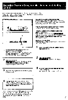
AAusting t a Digital Parametric Equalizer Characteristics of slope EQ level th12dB EQ center frequency 1kHz +12 +6 co S 0 -6 3 -12 20 4.0 20 100 1k 10k 20k Frequency (Hz) Note When All appears in the left upper portion of the display by pressing the EQ CH button, all three indications (FRONT, CENTER and REAR) appear in the right lower portion of the display. At this time, the front equalizer curve appears in the display. When returning to FRONT by pressing the EQ CH button, the equalizer curve of All is recalled in the display. When OVER appears in the display This shows that the input level is so high that the circuit clips. When listening to a program source connected to the analog input jacks, turn down the ANALOG input knob until the indication disappears. When listening to a program source connected to the digital input jacks, press the DIGITAL input button (-) until the indication disappears. To create a new equalization curve from the flat condition Press the EQ CH button (with the remote commander, press the EQUALIZER CH button) to select the desired channel. Then press the FLAT button. The designated channel becomes flat. Create a new equalization curve. Selecting the same center frequency for two or more frequency bands You can add the setting levels for each band together. As a result, if the same center frequency is set for all bands, the total of the levels for each band becomes the actual level for that center frequency; therefore, the level can be adjusted over a range from -36dB to +36dB. By setting the slope (O) to maximum, it is possible to reduce (notching) or raise (peaking) a signal at a specific frequency only. Any portion of the equalizer curve that exceeds *12dB will not be shown in the display, however. 42
-
 1
1 -
2
-
3
-
4
-
5
-
6
-
7
-
8
-
9
-
10
-
11
-
12
-
13
-
14
-
15
-
16
-
17
-
18
-
19
-
20
-
21
-
22
-
23
-
24
-
25
-
26
-
27
-
28
-
29
-
30
-
31
-
32
-
33
-
34
-
35
-
36
-
 37
37 -
 38
38 -
 39
39 -
 40
40 -
 41
41 -
 42
42 -
 43
43 -
 44
44 -
 45
45 -
 46
46 -
 47
47 -
48
-
49
-
50
-
51
-
52
-
53
-
54
-
55
 |
 |
