Brother International FAX-1010 Service Manual
Brother International FAX-1010 Manual
 |
View all Brother International FAX-1010 manuals
Add to My Manuals
Save this manual to your list of manuals |
Brother International FAX-1010 manual content summary:
- Brother International FAX-1010 | Service Manual - Page 1
FACSIMILE EQUIPMENT SERVICE MANUAL MODEL: FAX1170/1270/1570MC FAX1010/1020/1030 MFC1770/1870MC/1970MC - Brother International FAX-1010 | Service Manual - Page 2
© Copyright Brother 1997 All rights reserved. No part of this publication may be reproduced in any form or by any means without permission in writing from the publisher. Specifications are subject to change without notice. - Brother International FAX-1010 | Service Manual - Page 3
This publication is a Service Manual covering the specifications, construction, theory of operation, and maintenance of the Brother facsimile equipment. It includes information required for field troubleshooting and repair-disassembly, reassembly, and adjustment-so that service personnel will be - Brother International FAX-1010 | Service Manual - Page 4
CHAPTER I. GENERAL DESCRIPTION - Brother International FAX-1010 | Service Manual - Page 5
CONTENTS 1. EQUIPMENT OUTLINE I-1 1.1 External Appearance and Weight I-1 1.2 Components I-1 2. SPECIFICATIONS I-2 - Brother International FAX-1010 | Service Manual - Page 6
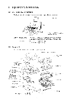
385 (D) * 317 mm for FAX1010 which has no handset mount Weight: Machine proper In package FAX1010: Approx. 5.0 kg (excluding a ribbon cartridge) Other models: Approx. 5.2 kg (excluding a ribbon cartridge) FAX1010: Approx. 8.7 kg Other models: Approx. 8.9 kg 1.2 Components The equipment consists - Brother International FAX-1010 | Service Manual - Page 7
Smoothing One-touch Dial Speed Dial Telephone Index Multi-resolution Transmission FAX/TEL Switch Distinctive Ringing Next Fax-reservation Help TAD Interface Coverpage Polling Type Receive Password (password plus) Delayed Transmission Call Reservation Call-back Message Speaker Phone Activity Report - Brother International FAX-1010 | Service Manual - Page 8
Fax-reservation Yes Yes Yes Help Yes, Simple Yes, Simple Yes, Simple TAD Interface Yes Yes Yes Coverpage Yes, Super Yes, Super Yes, Super Polling Type Std/Sec/Del/Seq Std/Sec/Del/Seq Std/Sec/Del/Seq Receive Password (password plus (Ready for France) Fax-Noice-on-demand No No - Brother International FAX-1010 | Service Manual - Page 9
Smoothing One-touch Dial Speed Dial Telephone Index Multi-resolution Transmission FAX/TEL Switch Distinctive Ringing Next Fax-reservation Help TAD Interface Coverpage Polling Type Receive Password (password plus) Delayed Transmission Call Reservation Call-back Message Speaker Phone Activity Report - Brother International FAX-1010 | Service Manual - Page 10
CHAPTER II. INSTALLATION - Brother International FAX-1010 | Service Manual - Page 11
CHAPTER III. THEORY OF OPERATION - Brother International FAX-1010 | Service Manual - Page 12
CONTENTS 1. OVERVIEW 1.1 Functional Block Diagram III-1 III-1 2. MECHANISMS III-2 2.1 Transmitting Mechanism (Feeding and scanning documents) III-2 2.1.1 Automatic document feeder (ADF) III-2 2.1.2 Scanner III-3 2.2 Receiving Mechanism (Feeding paper and printing data) III-4 2.3 Power - Brother International FAX-1010 | Service Manual - Page 13
OVERVIEW 1.1 Functional Block Diagram Control Panel LCD Recorder Recording head Scanner CIS unit Ribbon sensor Main frame Motor Document ejection tray Ribbon cartridge Modular PCB (Cover sensor) Main PCB (Document front and rear sensors) NCU PCB Power supply PCB Sensor PCB (Paper-edge sensor - Brother International FAX-1010 | Service Manual - Page 14
and document sensors. (For details about the sensors, refer to Section 2.4.) For the drive power source, refer to Section 2.3. Document Document support Document stacker Separation roller ADF parts Pressure roller, rear White pressure roller Pressure roller, front 0 O 0 (Front) Scanner (CIS unit - Brother International FAX-1010 | Service Manual - Page 15
2.1.2 Scanner The scanner uses a contact image sensor (CIS) unit which consists of an LED array illuminating documents, a self-focus lens array collecting the reflected light, a CIS PCB carrying out photoelectric conversion to output picture element data, and a cover glass on which a document - Brother International FAX-1010 | Service Manual - Page 16
about the sensors, refer to Section 2.4.) Paper Recording paper cover ASSY Thermal ink ribbon Paper feed roller ASSY ,/,-----: N 'tO O Co. a_ ) Chute the thermal recording head prints, as well as feeding the thermal ink ribbon. STEP 3: In the paper ejecting mode The same operation as for STEP - Brother International FAX-1010 | Service Manual - Page 17
further transmitted via the friction torque transmission ASSY to the ribbon drive gear ("e") which drives the ribbon take-up gear in the ribbon cartridge. Right side d (Gear 18) c (Gear 20/40) b (Gear 33RB) () 0 O • of 0 e (Gear 46 of Friction torque transmission ASSY) Main frame Platen frame - Brother International FAX-1010 | Service Manual - Page 18
2.3.2 Description of planetary gear system The equipment uses the following three planetary gear systems: - Sun gear 20/90 ("B" in the figure given on the previous page) and its planet gears - Sun gear 36/27 ("N") and its planet gear - Sun gear 39/24 ("R") and its planet gear This section - Brother International FAX-1010 | Service Manual - Page 19
2.3.3 Power transmission for four operation modes Depending upon the solenoid ON/OFF state and the motor rotation direction, the planetary gear train switches the power transmission route for the four operation modes. Solenoid ON/OFF state Solenoid: OFF Section 0 (to block the stoppper of arm B) \ - Brother International FAX-1010 | Service Manual - Page 20
[ 1 ] Scanning mode (Solenoid: OFF, Motor rotation: Reverse) In the scanning mode, the control electronics deactivates the solenoid. When the motor rotates in the reverse direction, the clutch lever turns counterclockwise with the spring so that its cutout ® becomes engaged with the stopper of arm - Brother International FAX-1010 | Service Manual - Page 21
[ 2 ] Paper feeding/ejecting mode (Solenoid: ON, Motor rotation: Reverse) In the paper feeding/ejecting mode, the control electronics activates the solenoid to release the stopper of arm A. When the motor rotates in the reverse direction, the sun gear 20/90 ("B") rotates clockwise so that the - Brother International FAX-1010 | Service Manual - Page 22
so as to drive the friction torque transmission ASSY and ribbon drive gear ("e") that rotates the ribbon take-up gear ("f") in the ribbon cartridge, as shown on the next page. C (Planet gear 20B) -----i.. B (Sun gear 20/90) -. $ ., O Cutout ® of clutch lever Stopper of arm A Clutch lever - Brother International FAX-1010 | Service Manual - Page 23
f (Ribbon take-up gear in the ribbon cartridge) , ( ) oj 0 /Platen frame b (Gear 33RB) (Front) d = Ribbon Friction torque drive gear transmission (Gear 24) ASSY (Gear 46) e \ Main frame Active Gears on the Right Side - Brother International FAX-1010 | Service Manual - Page 24
rotates so as to drive the friction torque transmission ASSY and ribbon drive gear ("e") that rotates the ribbon take-up gear ("f") in the ribbon cartridge, as shown on the next page. Stopper of arm B C (Planet gear 20B) Stopper of arm A Cutout ® of clutch lever B (Sun gear 20/90) O Clutch - Brother International FAX-1010 | Service Manual - Page 25
c ) f (Ribbon take-up gear in the ribbon cartridge) /Platen frame b (Gear 33RB) (Front) d = Ribbon Friction torque drive gear transmission (Gear 24) ASSY (Gear 46) e \ Main frame Active Gears on the Right Side III- 13 - Brother International FAX-1010 | Service Manual - Page 26
transmission ASSY (Gear 46) and ribbon drive gear (Gear 24) f: Ribbon take-up gear in the ribbon cartridge [ 1 ] Scanning Mode (Solenoid: OFF, Motor rotation: reverse) A -, B (Motor) C -,D -* E -,F -,G ... H (Separation L (Idling) roller) I (White pressure roller) J -, K (Document ejection - Brother International FAX-1010 | Service Manual - Page 27
[ 3 ] Recording Mode (Solenoid: OFF, Motor rotation: forward) n A•OB (Motor) < C•OM•ON L (Idling) Y • Z •0 a (Platen) •0 b • O 4+ P • Q 4 R -0 S • C 4 d• e • f (Ribbon take-up gear) W ',1 X (Paper ejection roller) V U4 T (Paper feed roller, Idling) [ 4 ] Copying Mode (Solenoid: ON, Motor - Brother International FAX-1010 | Service Manual - Page 28
presence of documents or paper. • Cover sensor which detects whether the recording paper cover ASSY is closed. • Ribbon sensor which detects whether the ink ribbon is loaded. • Hook switch sensor* which detects whether the handset is placed on the handset mount. The cover sensor has an actuator - Brother International FAX-1010 | Service Manual - Page 29
Main PCB 0 0 O 0 Document rear sensor Document rear sensor actuator Document front sensor Document front sensor actuator (Front) Front cover sensing actuator Paper-edge sensor actuator Paper-edge sensor Paper ejection sensor actuator Paper ejection sensor O O 0 (Front) iI Sensor PCB Recording - Brother International FAX-1010 | Service Manual - Page 30
I a O Cover sensor actuator Cover sensor lever @ Cover sensor Modular PCB Hook switch sensor actuator** Hook switch sensor** Hook switch PCB** Handset mount* Location of Sensors and Actuators (2) * Not provided on the FAX1010 ** Not provided on the FAX1010 or those versions equipped with a - Brother International FAX-1010 | Service Manual - Page 31
3. CONTROL ELECTRONICS 3.1 Configuration The hardware configuration of the facsimile equipment is shown below. Line \i iv External telephone Handset* 1111111 *2 PC l/F - Modular PCB I__I I__I 2-pin 2-pin 4-pin (Note) P2 8-pin NCU PCB *1 Main PCB - 5-pin Speaker ) CI Motor ICI Solenoid j 2- - Brother International FAX-1010 | Service Manual - Page 32
, recording, and power transmission shifting. D NCU 0 Power supply 0 Speaker D Modular PCB (for PC I/F) D Hook switch 0 sensor* Sensors ROM E2PROM = DRAM FAX engine (ASIC) Control panel Motor driver Recording head CIS Motor Sensors 0 Ni-MH battery 0 Microphone Not provided on the FAX1010 or - Brother International FAX-1010 | Service Manual - Page 33
Main PCB Circuit Diagram 1/5 C) FAX engine (ASIC) which integrates a CPU, digital portion of MODEM and gate array for managing the I/Os, memories, and drivers. ® XTI, oscillator for the CPU. ® XT3, oscillator for the calendar clock. ® XT2, oscillator for the MODEM. ® Reset IC which turns on at the - Brother International FAX-1010 | Service Manual - Page 34
). ® E2PROM (32-kilobit for the FAX1570MC/1030/MFC1970MC, 16-kilobit for other models.) ® ROM (2-megabit. Note that the qualification machines for demonstration have a 4megabit ROM.) C) DRAMs (1-megabyte, two 4-megabit chips) provided on the FAX1570MC/1030/ MFC1970MC. C) DRAM (512-kilobyte - Brother International FAX-1010 | Service Manual - Page 35
compensating the DC component of video signals for the next scan line. Working with the FAX engine, this circuitry carries out the standard scanning. (This circuitry is provided on the FAX1170/1270/1010/1020/MFC1770/1870MC.) ®-7 SANYO LSI that carries out the high-quality scanning. (Provided on the - Brother International FAX-1010 | Service Manual - Page 36
switching analog selectors ®-1: Switches between the output line and input line for monitoring. When switched to the output line, this selector allows FAX sending operation to be monitored; when switched to the input line, it allows received voices to be monitored. ®-2: Selects either voice signals - Brother International FAX-1010 | Service Manual - Page 37
0 Connector for the speaker 0 , Speaker volume control circuit (:)-1: VOL1 OFF ON ON (:)-2: VOL2 OFF OFF ON (:)-3: VOL3 OFF OFF ON Speaker volume High Medium Low (ON: Closed OFF: Opened) III - 25 - Brother International FAX-1010 | Service Manual - Page 38
• Main PCB Circuit Diagram 515 C) Connector for the microphone C) Voice signal amplifier circuit ® Analog portion of MODEM These are provided on the FAX1570MC/ 1030/MFC1870MC/1970MC. III - 26 - Brother International FAX-1010 | Service Manual - Page 39
3.3 NCU PCB The NCU PCB switches the communications line to telephone or built-in MODEM, under the control of the main PCB. JI 2 - Al A2 .tan, enx 13!2P111 L3 L4 -i> JS 11 LO 0200X. ::5R200P.X. L DI 199120 R3 1000 20 O ,=02 22 ,__,CC OBI S1YB4D or ::AIE 0 R20 100o 7I!;627 039'2'6'39 gS9 - Brother International FAX-1010 | Service Manual - Page 40
JP3 Dx-au C32 THe S It JP car .5V0 104. I na 156120%2 J L2 23061 ..4 a T 02 W2 RaH 600V J P L343071 R62 9071 (I0) PH3 TLPI1271 (suilire4a or Si -K1- ERAI5-04 44-7( 012 ° I_ - CR2 TX -0 g7C1 14YK SOY .SP9 JP al C) LI > C4 BP OP 50 C28 Oa c1a a„ CI CC563 n lP 54 4 R II BTS - Brother International FAX-1010 | Service Manual - Page 41
provided on the FAX1170/1270/1010/1020/MFC1770), which are controlled by the gate array according to commands issued from the FAX engine on the main PCB rubber keytops. Main PCB i Control Panel PCB FAX Engine SIDN SDOUT PCLK +5V RESET > Backup Circuit }Serial > Communications > Ports Gate - Brother International FAX-1010 | Service Manual - Page 42
3.5 Power Supply PCB The power supply uses the switching regulation system to generate DC power (+25V and +8V) from a commercial AC power supply. The +25V source is stabilized and fed to the motor and solenoid for feeding documents and recording paper, the main PCB, and also fed to the CIS LED array - Brother International FAX-1010 | Service Manual - Page 43
CHAPTER IV. DISASSEMBLY/REASSEMBLY AND LUBRICATION - Brother International FAX-1010 | Service Manual - Page 44
Handset Mount 1.15 Side Covers R and L 1.16 Speaker and Battery 1.17 Document Front Sensor Actuator 1.18 Main Frame 1.19 Separation Roller, its Support, and Document Rear Sensor Actuator 1.20 Document Ejection Roller and CIS Leaf Spring 1 21 Motor 1 22 Solenoid 1 23 Drive Gears 1 24 Friction Torque - Brother International FAX-1010 | Service Manual - Page 45
1. DISASSEMBLY/REASSEMBLY ■ Safety Precautions To prevent the creation of secondary problems by mishandling, observe the following precautions during maintenance work. (1) Always turn off the power before replacing parts or units. When having access to the power - Brother International FAX-1010 | Service Manual - Page 46
Tightening Torque List Location Screw type Recording head ASSY Screw, cup S 3x6 Recording paper cover ASSY Taptite, cup S 3x8 Chute ASSY Taptite, cup S 3x8 Paper feed chute Taptite, cup S 3x8 Panel rear cover Taptite, cup B 3x8 Inner cover Taptite, cup S 3x8 CIS holders R and L - Brother International FAX-1010 | Service Manual - Page 47
below.) (2) Remove - the paper wire extension, - the paper support, - the document support, - the document ejection tray, and - the ribbon cartridge. Ribbon cartridge Handset and curled cord* Telephone line cord Document support Paper support Paper wire extension BT modular jack adapter (provided - Brother International FAX-1010 | Service Manual - Page 48
CIS unit Side cover L (;) Side cover R Speaker Battery 18 Main frame °Document front sensor actuator cp Separation roller and its support 0 ?Document rear sensor actuator Cri) CIS leaf spring Document ejection roller 21 Motor Cr) Solenoid Friction torque transmission ASSY, related gears - Brother International FAX-1010 | Service Manual - Page 49
1.1 Recording Head ASSY (1) Push the open button and fully open the recording paper cover ASSY. Open button Recording paper cover ASSY (t) .O 000 ccs=':Dc2c:' o0 00 cOD CD CP o (2) As shown below, insert the tip of a flat screwdriver into the square hole and release the hook "x" of the ROM - Brother International FAX-1010 | Service Manual - Page 50
Head-power harness Lock of relay connector \?> Recording head ASSY ltiNj I ------- ADOo 0 O0 Main-head harness Head-power harness FAX1170/1270/1010/1020/MFC1770 FAX1570MC/1030/MFC1870MC/1970MC (NCU connector) Main-head harness (NCU connector) (Modular PCB connector) " Ps "I= P7 21=10 - Brother International FAX-1010 | Service Manual - Page 51
(7) To disassemble the recording head ASSY, follow the steps below. 1) Remove the head protection plate by unhooking the two latches. 2) Turn the recording head ASSY upside down and release the head-power harness from the adhesive tape. 3) Place the recording head ASSY rightside up. 4) Push down - Brother International FAX-1010 | Service Manual - Page 52
, insert the tip of a flat screwdriver as shown below and twist it to release two latches of each paper guide from the recording paper cover. NOTE: Once removed, those paper guides will become unusable and new parts will have to be put back in. (3) Remove the two screws. (4) Push the open button - Brother International FAX-1010 | Service Manual - Page 53
1.3 Platen (1) At the left end of the platen, remove the platen gear (Gear 23) by pulling its pawl outwards and then remove the bushing. (2) At the right end, remove the gear 33RB by pulling its pawl outwards and then remove the bushing. (3) Move the platen to the left to take out the right end from - Brother International FAX-1010 | Service Manual - Page 54
1.4 Lock Levers and Their Shaft (1) At each end of the lock lever shaft, release the lock spring from the lock lever and the platen frame. (2) Turn the lock lever R clockwise (when viewed from the right side) and pull it out from the shaft. Then, the lock lever L, lock springs, and lock lever shaft - Brother International FAX-1010 | Service Manual - Page 55
1.5 Chute ASSY (1) Remove the two screws. (2) Move the chute ASSY to the left to release tab "a" from the platen frame, pull the chute ASSY towards you, and take it out. Chute ASSY Platen frame. Tab "a" Tab "b" Chute ASSY 0 o 0 Tab "a" Tab "b" "b" 0 Cutout CDCD c5=S:p ■ Reassembling Notes - Brother International FAX-1010 | Service Manual - Page 56
1.6 Paper Feed Roller ASSY and Paper Feed Sub Chute (1) Remove the front cover sensing actuator from the paper feed roller shaft by pulling up the actuator's rear edge as shown below. Front cover sensing actuator Paper feed roller ASSY (Front) ti) N Pull up here to remove. Platen frame o - Brother International FAX-1010 | Service Manual - Page 57
(4) At the either end of the paper feed sub chute, release the latch from the paper feed chute with a flat screwdriver as illustrated below, and then pull up the paper feed sub chute. Paper feed sub chute Slot provided in the paper feed chute Sub chute film Latch Latch Paper feed chute Platen - Brother International FAX-1010 | Service Manual - Page 58
roller gear (Gear 55) Sun gear 39/24 • When setting the front cover sensing actuator onto the paper feed roller shaft, make sure that it supports the boss of the paper-edge sensor actuator as shown on the previous page. - Brother International FAX-1010 | Service Manual - Page 59
1.7 Paper Feed Chute, Sensor PCB, and Paper-edge and Paper Ejection Sensor Actuators (1) Remove the two screws. (2) Remove the sensor PCB by releasing the two latches. (3) Disconnect the main-sensor harness from the sensor PCB. (4) Pull up the lead wires of the main-sensor harness out of the sheath, - Brother International FAX-1010 | Service Manual - Page 60
Paper ejection sensor (PH1) Paper-edge sensor (PH2) , w ,y , a _.------7 ,/ / / / , / / / Paper-edge sensor actuator -------N 7i 7 O Paper feed chute (Rear) Support "x" Separator pad Spring Paper ejection sensor (PH1) Sensor PCB Paper-edge sensor (PH2) (Rear) Main-sensor harness connector - Brother International FAX-1010 | Service Manual - Page 61
1.8 Paper Ejection Roller (1) At the left end of the paper ejection roller (when viewed from the rear), remove the bushing by pulling its pawls outwards. (2) At the right end, remove the paper ejection roller gear (Gear 40) by pulling its pawl outwards. Next, take out the paper ejection roller - Brother International FAX-1010 | Service Manual - Page 62
1.9 Gears on the Platen Frame Gears 18/41 Paper ejection roller gear (Gear 40) Platen frame Clutch gear ASSY Paper feed roller gear Planet gear 34 of the arm P ASSY Sun gear 39/24 (Gears 18/41) W (Clutch gear ASSY) X (Paper ejection roller gear, Gear 40) U T (Paper feed roller gear, Gear - Brother International FAX-1010 | Service Manual - Page 63
1.10 Control Panel ASSY (1) Remove the ROM cover, referring to Section 1.1, steps (1) and (2). (2) Disconnect the main-panel harness and the main-mike harness (for the FAX1570MC/ 1030/MFC1870MC/1970MC) from the main PCB. (3) Slightly open the control panel ASSY as shown below. (4) Push the right and - Brother International FAX-1010 | Service Manual - Page 64
FAX1170/1270/1010/1020/MFC1770 (NCU connector) Main-panel harness (Modular PCB connector) I- - I DICI " I, 4 i c 3 P7 P9= E a 0 0 . I 1 P2 Main PCB o (Front) FAX1570MC/1030/MFC1870MC/1970MC (NCU connector) Main-panel - Brother International FAX-1010 | Service Manual - Page 65
put back in. (6) To take out the control panel PCB and the FPC key, unhook the PCB from the two latches ("Y" on the FAX1170/1270/1010/1020/MFC1770, "Z" on the FAX1570MC/1030/ MFC1870MC/1970MC) on the control panel. Unlock the LCD cable connector and disconnect the LCD flat cable. (7) To separate - Brother International FAX-1010 | Service Manual - Page 66
(8) To take out the LCD, remove the control panel PCB and the FPC key in step (6). As shown below, insert the tip of a flat screwdriver under clamp "D" in the direction of arrow F and push up clamp "D" slightly to release the LCD from clamp "C." In the same way, insert the screwdriver under clamp - Brother International FAX-1010 | Service Manual - Page 67
1.12 Inner Cover (1) Remove the four screws. (2) While lifting up the inner cover, release the five latches with the tip of a flat screwdriver. 5 latches Inner cover - IV - 23 - Brother International FAX-1010 | Service Manual - Page 68
roller err Bushing R White pressure roller gear Bushing L Pull here towards you. (2) Disconnect the CIS harness from the main PCB. FAX1170/1270/1010/1020/MFC1770 (NCU connector) noP3 PP4L P5 ----tf (Modular PCB connector) IPt] ' P9= P7 a ID O /72 CIS harness Main PCB (Front) FAX1570MC - Brother International FAX-1010 | Service Manual - Page 69
(3) Tilt the CIS unit towards you to release the rear latches from the main frame, and the CIS unit comes off. Rear latch C S harness c ."" Leaf spring CIS unit CIS holder Front latch (4) Remove the CIS holders R and L as shown below. er, CIS holder, L CIS holder, R O O CIS unit CIS harness - Brother International FAX-1010 | Service Manual - Page 70
1.14 Handset Mount (for models except the FAX1010) Side Cover (for the FAX1010) (1) Disconnect the hook switch harness* from the main PCB. (2) Remove the two screws from the handset mount* or the side cover**. (3) Twist the handset mount* or the side cover** so that it tilts over to the left and - Brother International FAX-1010 | Service Manual - Page 71
1.15 Side Covers R and L (1) Lift up the front of the side cover R and take it out. (2) Disconnect the main-sensor harness from the main PCB, and then lift up the front of the side cover L and take it out together with the main-sensor harness. Platen frame Side cover L 0 GMD Hole Routing of the - Brother International FAX-1010 | Service Manual - Page 72
FAX1170/1270/1010/1020/MFC1770 FAX1570MC/1030/MFC1870MC/1970MC (NCU connector) 17 El = a (Modular PCB connector) P4 P5 P8 - =.------ Pg= P7 '71=1O a Mainsensor harness (Modular PCB connector) ( - Brother International FAX-1010 | Service Manual - Page 73
O Speaker harness Document front sensor actuator Battery Battery harness (Provided on the FAX1570MC/1030/ MFC1870MC/1970MC) FAX1170/1270/1010/1020/MFC1770 (NCU connector) FAX1570MC/1030/MFC1870MC/1970MC (NCU connector) (Modular PCB connector) O /F 1 P9= P7 El= A-Din1741P10 1:1aP1 - Brother International FAX-1010 | Service Manual - Page 74
1.17 Document Front Sensor Actuator (1) As shown below, push down the latch of the right end of the document front sensor actuator to release it from the hole provided in the main frame, move it to the left, and then lift it up. D e9' c ' , ..-'`-' "...,,,-. 'N.,.....,' -. VD ... I .0. kl - Brother International FAX-1010 | Service Manual - Page 75
Equipment placed upright n @ ® e ,--- Bottom plate „a„ (3) Place the machine rightside up. (4) Disconnect the following four harnesses from the main PCB: • the lock of the relay connector to release. FAX1170/1270/1010/1020/MFC1770 Ferrite core Power-main harness Main-head harness T-shaped - Brother International FAX-1010 | Service Manual - Page 76
FAX1570MC/1030/MFC1870MC/1970MC Ferrite core Power-main harness Main-head harness T-shaped boss Motor harness Solenoid harness Motor Main PCB 0 (Front) (6) Remove four screws "b" and lift up the main frame. "b" Head-power harness (Relay connector) c:D 1 3 01 ,425a:Z. - O Main frame Main - Brother International FAX-1010 | Service Manual - Page 77
1.19 Separation Roller, its Support, and Document Rear Sensor Actuator (1) At the left side of the main frame, remove the gr. Latch (4) As shown below, release the latch with the tip of a flat screwdriver and slide the separation roller support to the right and lift it up. Latch Separation roller - Brother International FAX-1010 | Service Manual - Page 78
(5) To remove the document rear sensor actuator, push down the latch of its right end to release it from the hole provided in the main frame, move it to the left, and then take it out. Document rear sensor actuator e9' ) A 1 4 . Push here. - Brother International FAX-1010 | Service Manual - Page 79
1.20 Document Ejection Roller and CIS Leaf Spring (1) To remove the document ejection roller, pull out the gear 14/20 by pulling its pawl outwards. Next, move the document ejection roller to the left and take it out downwards. .r D fo 0 0 I (@) .., o 0 1 ... o 5 . vs. Gear 14/20 1 - Brother International FAX-1010 | Service Manual - Page 80
1.21 Motor (1) To remove the motor, at the left side of the main frame, unhook the spring and then pull out the clutch lever by pulling its pawl outwards. Next, remove the screw and turn the motor clockwise when viewed from the left. Motor Clutch lever and spring I 1 - Brother International FAX-1010 | Service Manual - Page 81
1.22 Solenoid (1) At the left side of the main frame, remove the spring and pull out the clutch lever by pulling its pawl outwards. (2) Remove the gear 20/40. (3) Remove the arm B ASSY and arm AASSY by pulling the arm B's pawl outwards. (4) Push up the clamp and remove the solenoid. Solenoid Arm - Brother International FAX-1010 | Service Manual - Page 82
1.23 Drive Gears (1) At the left side of the main frame, remove the clutch lever, gears, and arm ASSYs, by pulling their pawls outwards (if any). Gear 33 Gear 18 N \ 5 Gear 33/45 Gear 39 Cover sensor actuator Comfy Actuator spring Arm C ASSY (Planet gear 44) Sun gear 36/27 Arm B ASSY (Planet - Brother International FAX-1010 | Service Manual - Page 83
1.24 Friction Torque Transmission ASSY, its Related Gears, and Slip Gear 40 (1) At the right side of the main frame, remove the ribbon drive gear (Gear 24) by pulling its two pawls outwards. (2) Remove the screw and take off the friction holder. (3) Remove the gear 18 by pulling its pawl outwards - Brother International FAX-1010 | Service Manual - Page 84
ribbon bushings B. Pawled ribbon bushing B Pawled ribbon bushing B Ribbon bushing e9' Main frame Ribbon bushing czg 1.26 Bottom Plate (1) Place the machine upside down. (2) Remove the six screws from the bottom plate. (3) Slightly lift up the bottom plate and disconnect the grounding terminal - Brother International FAX-1010 | Service Manual - Page 85
27 Main PCB, NCU PCB and Modular PCB (1) Place the machine rightside up. (2) Disconnect the following harnesses from the main PCB For the FAX1570MC/1030/MFC1870MC/1970MC • Battery harness (2-pin) FAX1170/1270/1010/1020/MFC1770 FAX1570MC/1030/MFC1870MC/1970MC Hook switch harness* Main-panel harness - Brother International FAX-1010 | Service Manual - Page 86
(3) Turn the machine upside down. (4) Unhook the modular PCB from the latches, slightly lift up front edge of the main PCB, and then take out the main PCB - Brother International FAX-1010 | Service Manual - Page 87
PCB (1) Place the machine rightside up. (2) Disconnect the power-main harness from the main PCB. (3) Disconnect the relay connector of the head-power harness. NOTE: To disconnect the relay connector, push the lock of the relay connector to release. FAX1170/1270/1010/1020/MFC1770 FAX1570MC/1030 - Brother International FAX-1010 | Service Manual - Page 88
(4) Turn the machine upside down. (5) Remove the adhesive tape to release the power-main harness and the head-power har- ness. (6) Lift up the power supply PCB and - Brother International FAX-1010 | Service Manual - Page 89
1.29 Harness Routing FAX1170/1270/1010/1020/MFC1770 Power-main harness Main-head harness Main-sensor harness T-shaped boss Motor harness Solenoid harness Head-power harness (Relay connector) Center beam of - Brother International FAX-1010 | Service Manual - Page 90
2. LUBRICATION Apply the specified lubricants to the lubrication points as shown below. Molykote EM-30L For points ®, apply a rice-sized pinch of grease (6 mm3). For points ®, apply a bean-sized pinch of grease (12 mm3). Floil GE-334C For points ®, apply half of a rice-sized pinch of grease (3 mm3). - Brother International FAX-1010 | Service Manual - Page 91
[ 3 ] Gears at the left side of the platen frame Platen frame 0 Platen Clutch gear ASSY Clutch gear ASSY Arm P ASSY [ 4 ] Paper ejection roller Paper ejection roller Paper ejection roller gear (Gear 40) 0 Pawled bushing 0 Platen frame (Rear) IV - 47 - Brother International FAX-1010 | Service Manual - Page 92
[ 5 ] Gears at the left side of the main frame go' 6 Arm C ASSY Arm A ASSY 0 0 Arm B ASSY Main frame [ 6 ] Friction torque transmission ASSY at the right side of the main frame Gear 46 ASSY IV - 48 - Brother International FAX-1010 | Service Manual - Page 93
[ 7 ] Separation roller and document ejection roller Separation roller 0 A 4 ©3 0 Separation roller support Document ejection roller IV - 49 - Brother International FAX-1010 | Service Manual - Page 94
CHAPTER V. MAINTENANCE MODE - Brother International FAX-1010 | Service Manual - Page 95
CONTENTS 1. ENTRY INTO THE MAINTENANCE MODE 2. LIST OF MAINTENANCE-MODE FUNCTIONS 3. DETAILED DESCRIPTION OF MAINTENANCE-MODE FUNCTIONS 3.1 E2PROM Parameter Initialization 3.2 Printout of Scanning Compensation Data 3.3 ADF Performance Test 3.4 Test Pattern 1 3.5 Firmware Switch Setting and Printout - Brother International FAX-1010 | Service Manual - Page 96
1. ENTRY INTO THE MAINTENANCE MODE To make the facsimile equipment enter the maintenance mode, press the Function * 2 8 , 6 , and 4 keys in this order. k Within 2 seconds- The equipment beeps for approx. one second and displays " II MAINTENANCE 171 " on the LCD, indicating that it is placed in the - Brother International FAX-1010 | Service Manual - Page 97
2. LIST OF MAINTENANCE-MODE FUNCTIONS Function Code 01 02 03 04 05 06 07 08 09 10 11 12 13 14 15 32 Maintenance-mode Functions Function E2PROM Parameter Initialization Printout of Scanning Compensation Data ADF* Performance Test Test Pattern 1 Firmware Switch Setting Printout of Firmware Switch - Brother International FAX-1010 | Service Manual - Page 98
user-accessible selectors which are shaded in the firmware switch tables in Subsection 3.5. The service personnel should instruct end users key. FAX1170/1270/1010/1020/MFC1770 Function key brother LIM1970MC Set heiction Mar ► !Mm LI 11wN • &NA Resolution • FAX f 41227.0 212219 00. • - 7i0"41 FAX - Brother International FAX-1010 | Service Manual - Page 99
E2PROM areas, but entering 91 does not initialize some areas, as listed below. Data item Function code Maintenance-mode functions User switches Firmware switches Remote activation code Activity report Distinctive ringing patterns registered (only for the U.S.A. versions) Station ID data Outside - Brother International FAX-1010 | Service Manual - Page 100
3.2 Printout of Scanning Compensation Data ■ Function The equipment prints out the white and black level data for scanning compensation. ■ Operating Procedure Do not start this function merely after powering on the equipment but start it after carrying out a sequence of scanning operation. Unless - Brother International FAX-1010 | Service Manual - Page 101
5F00 : DD DE E3 DF E6 EB F4 EA 5F10 F6 F4 ED EB F3 FD F9 F6 5F20 : ES E9 E4 E6 E0 E6 E8 ES 5F30 : D7 D4 D1 D8 D6 D5 D1 C7 5F40 : 5F50 : 5F60 nr 38 31 3F 5F70 : 29 24 ,L? 5F80 : OF DB D5 CB D5 DC D7 D1 5F90 : D5 DB DE El E4 EO DE D4 5FAO : E3 E4 E4 DA DF DC DD D5 5FB0 : CB D1 D3 D6 D2 CF - Brother International FAX-1010 | Service Manual - Page 102
3.3 ADF Performance Test ■ Function The equipment counts the documents fed by the automatic document feeder (ADF) and displays the count on the LCD for checking the ADF performance. ■ Operating Procedure (1) Set documents. (Allowable up to the ADF capacity.) The "DOC. READY" will appear on the LCD. - Brother International FAX-1010 | Service Manual - Page 103
3.4 Test Pattern 1 ■ Function This function, much like the copying function, prints out test pattern 1 to allow the service personnel to check for record data missing or print quality. ■ Operating Procedure Press the 0 and 9 keys in this order in the initial maintenance mode. The - Brother International FAX-1010 | Service Manual - Page 104
3.5 Firmware Switch Setting and Printout [A ] Firmware switch setting ■ Function The facsimile equipment incorporates the following firmware switch functions (WSW01 through WSW34) which may be activated with the procedures using the control panel keys and buttons. The firmware switches have been - Brother International FAX-1010 | Service Manual - Page 105
minute after a single-digit number is entered for double-digit firmware switch numbers, the equipment will automatically return to the initial maintenance mode. ■ Note The user-accessible selectors of the firmware switches are shaded in the tables given on the following pages. - Brother International FAX-1010 | Service Manual - Page 106
• Detailed Description for the Firmware Switches WSW01 (Dial pulse setting) Selector No. Function 1 Dial pulse generation mode 2 3 Break time length in pulse 4 dialing Setting and Specifications No. 1 2 00 : 01 : 10 : 11 : No. 3 4 00 : 01 : 10 : 11 : N N+1 10-N N 60 ms 67 ms 40 ms (for 16 - Brother International FAX-1010 | Service Manual - Page 107
(PB) dialing This selector sets the default dialing mode (pulse dialing or tone dialing) which may be changed by the function switch. If the user switches it with the function switch when selector 7 is set to "0," the setting specified by this selector will be also switched automatically. WSW02 - Brother International FAX-1010 | Service Manual - Page 108
signal upon detection of CNG signals by the number of cycles specified by these selectors and then starts FAX reception. Selector No.1 No. 5 0 (A) 0 (A) 1 (B) 1 (B) 0 (A) 1 (B) 0 (A) 1 (B) Cycle No detection One cycle 1.5 cycles 2 cycles • Selectors 2 through 4: Min. detection time length of - Brother International FAX-1010 | Service Manual - Page 109
• Selectors 6 and 7: Dial tone detection in PABX These selectors activate or deactivate the dial tone detection function which detects a dial tone when a line is connected to the PABX. Setting both of these selectors to "1" activates the dial tone detection function so that the equipment starts - Brother International FAX-1010 | Service Manual - Page 110
10 : 11 : 1810 ms 250 ms 500 ms NOTE: Selectors 1 and 5 through 8 are not applicable in those countries where no transfer facility is supported. • Selector 1: Earth function in transfer facility This selector determines whether or not the earth function is added to the transfer setting menu to be - Brother International FAX-1010 | Service Manual - Page 111
function so that the equipment starts dialing upon detection of a dial tone when a line is connected. (However, in those countries which support no dial tone detection function, e.g., in the U.S.A., setting these selectors to "1" makes the equipment start dialing after a WAIT of 3.5 seconds.) For - Brother International FAX-1010 | Service Manual - Page 112
• Selectors 5 and 6: Busy tone detection in automatic sending mode These selectors determine whether or not the equipment automatically disconnects a line upon detection of a busy tone in automatic sending mode. Setting selector 6 to "0" ignores a busy tone so that the equipment does not disconnect - Brother International FAX-1010 | Service Manual - Page 113
Twice 1: 50 ms NOTE: Selectors 4 through 8 are not applicable in those countries where no dial tone detection is supported, e.g., U.S.A. • Selectors 1 through 3: PAUSE key setting and 2nd dial tone detection Selectors 12 3 0 0 0 0 0 1 0 1 0 0 1 1 1 0 0 1 0 1 1 1 0 1 1 1 No WAIT is inserted even - Brother International FAX-1010 | Service Manual - Page 114
activated by selectors 1 through 3 (Setting 1, 1, 0 or 1, 1, 1). This function does not apply in those countries where no dial tone detection function is supported. • Selector 7: No. of dial tone detection times This selector sets the number of dial tone detection times required for starting dialing - Brother International FAX-1010 | Service Manual - Page 115
-42 dBm 0: 30 ms 1: 50 ms NOTE: The WSW07 is not applicable in those countries where no dial tone or line current detection is supported, e.g., U.S.A. • Selectors 1 and 2: Frequency band range These selectors set the frequency band for the 1st dial tone and the busy tone (before dialing) to be - Brother International FAX-1010 | Service Manual - Page 116
dBm -36 dBm -39 dBm -42 dBm NOTE: The WSW08 is not applicable in those countries where no dial tone or line current detection is supported, e.g., U.S.A. • Selectors 1 through 3: 1st dial tone detection time length Upon detection of the 1st dial tone for the time length set by these selectors, the - Brother International FAX-1010 | Service Manual - Page 117
: Selectors 1 through 5 are not applicable in those models which do not support ECM. • Selector 1: Frame length selection Usually a single frame consists of 256 set to "0," the equipment may use non-standard commands (the machine's native-mode commands, e.g., NSF, NSC, and NSS) for communications - Brother International FAX-1010 | Service Manual - Page 118
WSW10 (Protocol definition 2) Selector No. 1 2 3 4 Function Switching of DPS, following the CML ON/OFF Time length from transmission of the last dial digit to CML ON Time length from CML ON to CNG transmission Time length from CML ON to CED transmission (except for facsimile-to-telephone switching - Brother International FAX-1010 | Service Manual - Page 119
410/320-550 ms 1: 100-660/100-660 ms NOTE: The WSW11 is not applicable in those countries where no busy tone detection is supported, e.g., U.S.A. The setting of WSW11 is effective only when selectors 5 and 6 of WSW05 are set to "0, 1" or "1, 1" (Busy tone detection). • Selectors 1 and 2: Frequency - Brother International FAX-1010 | Service Manual - Page 120
Selector No. 1 2 3 4 5 6 7 8 WSW12 (Signal detection condition setting) Function Min. OFF time length of calling signal (Ci) Max. OFF time length of calling signal (Ci) Detecting time setting Delay Not used. Setting and Specifications No. 1 2 00 : 01 : 10 : 11 : No. 3 4 00 : 01 : 10 : 11 : No. 5 - Brother International FAX-1010 | Service Manual - Page 121
1 : -51 dBm 5 1 Modem attenuator 8 0: 0dB 0: 0 dB 0: 0dB 0: 0 dB 1: 8 dB 1: 4 dB 1: 2 dB 1: 1 dB The modem should be adjusted according to the user's line conditions. • Selectors 1 and 2: Cable equalizer These selectors are used to improve the pass-band characteristics of analogue signals on - Brother International FAX-1010 | Service Manual - Page 122
: 30 Hz 55 Hz 70 Hz 5 No. of rings in AUTO ANS I mode 8 No. 5 6 7 8 0000 : 0001 : 0010 : 0 011 : 0100 : 0101 : 0110 : 0111 : 1000 : 1001 : 1010 : 1011 : 110 0 : 1101 : 1110 : 1111 : Fixed to once Fixed to 2 times Fixed to 3 times Fixed to 4 times 1 to 2 times 1 to 3 times 1 to 4 times 1 to - Brother International FAX-1010 | Service Manual - Page 123
WSW15 (REDIAL facility setting) Selector No. Function 1 Selection of redial interval 2 3 1 No. of redialings 6 7 Not used. 8 Setting and Specifications No. 1 2 00 : 01 : 10 : 11 : 5 minutes 1 minute 2 minutes 3 minutes No. 3 4 5 6 0 0 0 0 : 16 times 0 0 0 1 : 1 time 0 0 1 0 : 2 times 0 - Brother International FAX-1010 | Service Manual - Page 124
sharing a modular wall socket with the equipment, as well as from the directly connected external telephone. If any of the following problems occurs frequently, set this selector to "0": • Dialing from any of the telephones sharing a modular wall socket starts the facsimile equipment. • Picking - Brother International FAX-1010 | Service Manual - Page 125
WSW17 (Function setting 2) Selector No. Function 1 Off-hook alarm 2 3 Power failure report output 4 Calendar clock/prompt alternate display 5 Calendar clock type 6 Error indication in activity report 7 Non-ring reception 8 Not used. Setting and Specifications No. 1 2 00 : 01 : 1X : - Brother International FAX-1010 | Service Manual - Page 126
WSW18 (Function setting 3) Selector No. 1 Function CCD manufacturer setting 2 Detection enabled time for CNG 3 and no tone 4 5 Not used. 6 Registration of station ID 7 Tone sound monitoring 8 Setting and Specifications Fixed to 1. No. 2 3 00 : 01 : 10 : 11 : 40 sec. 0 sec. (No - Brother International FAX-1010 | Service Manual - Page 127
WSW19 (Transmission speed setting) Selector No. Function 1 First transmission speed choice 3I for fallback 4 Last transmission speed choice 6 for fallback Setting and Specifications No. 1 2 3 No. 4 5 6 0 0 0 : 2,400 bps 0 0 1 : 4,800 bps 0 1 0 : 7,200 bps 0 1 1 : 9,600 bps 1 0 0 : 12,000 - Brother International FAX-1010 | Service Manual - Page 128
WSW20 (Overseas communications mode setting) Selector No. 1 2 Function EP*tone prefix Overseas communications mode (Reception) Setting and Specifications 0: OFF 1: ON 0: 2100 Hz 1: 1100 Hz 3 Overseas communications mode (Transmission) 0: OFF 1: Ignores DIS once. No. 4 5 4 Min. time - Brother International FAX-1010 | Service Manual - Page 129
WSW21 (TAD setting 1) Selector No. Function Setting and Specifications No. 1 2 3 4 5 0 0 0 0 0 : No detection 0 0 0 0 1 : 1 sec. 1 I Max. waiting time for voice signal 5 0 0 0 1 0 : 2 sec. 0 0 0 1 1 : 3 sec. I I 0 1 0 0 0 : 8 sec. I I 1 1 1 1 1 : 31 sec. 6 Two-way recording 7 - Brother International FAX-1010 | Service Manual - Page 130
WSW23 (Communications setting) Selector No. 1 Function Starting point of training check (TCF) 2 Allowable training error rate 3 Setting and Specifications 0: From the head of a series of zeros 1: From any arbitrary point No. 2 3 00 : 01 : 10 : 11 : 0% 0.5% 1% 2% 4 Decoding error rate for 5 - Brother International FAX-1010 | Service Manual - Page 131
WSW24 (TAD setting 2) Selector No. Function 1 Maximum OGM recording time 2 Setting and Specifications No. 1 2 00 : 01 : 10 : 11 : 15 sec. 20 sec. 30 sec. 50 sec. 3 Time length from CML ON to start of pseud ring backtone 4 transmission No. 3 4 00 : 01 : 10 : 11 : 4 sec. 3 sec. 2 sec. 1 - Brother International FAX-1010 | Service Manual - Page 132
WSW25 (TAD setting 3) Selector No. 1 I 4 Function Not used. Setting and Specifications No. 5 6 7 0 0 0 : 2 sec. 0 0 1 : 4 sec. 5 Pause between paging number and PIN 7 010 : 011 : 100 : 6 sec. 8 sec. 10 sec. 1 0 1 : 12 sec. 1 1 0 : 14 sec. 1 1 1 : 16 sec. Automatic shift to facsimile - Brother International FAX-1010 | Service Manual - Page 133
version of the facsimile equipment is set up for the British Telecom's caller ID service or its equivalent. Selector 2 takes effect only when selector 1 is set TAD mode or via the facsimile equipment in FT mode. • Selector 8: FAX reception after the time-out of pseudo ring backtones in FIT mode If - Brother International FAX-1010 | Service Manual - Page 134
WSW27 (Function setting 5) Selector No. 1 2 3 4 5 Function Not used. Ringer OFF setting Automatic playback of OGM at the start time of OGM ON mode Detection of distinctive ringing pattern Automatic erasure of voice alarm Setting and Specifications 0: YES 0: NO 0: NO 0: YES 1: NO 1: YES 1: YES - Brother International FAX-1010 | Service Manual - Page 135
WSW28 (Function setting 6) Selector No. Function 1 Transmission level of DTMF high-band frequency signal 3 4 Transmission level of DTMF low-band frequency signal 6 Setting and Specifications No. 1 2 3 000 : 001 : 010 : 011 : 100 : 101 : 110 : 111 : 0dB +1 dB +2 dB +3 dB 0 dB -1 dB -2 dB -3 dB - Brother International FAX-1010 | Service Manual - Page 136
Note below) can be accessed. If it is set to "0," caller IDs stored in the memory can be called up on the LCD by the user function 6-7 and then pressing the Start key when the desired caller ID is displayed dials the caller automatically. (Note: The equipment can store a maximum of - Brother International FAX-1010 | Service Manual - Page 137
WSW30 (Function setting 8) Selector No. Function 1 Detection level of dial tone or I busy tone for the built-in TAD operation 3 4 Not used. 5 Speaker output level 6 Not used. 7 Recording intensity control 8 Setting and Specifications No. 1 2 3 0 0 0 : -38.0 dBm (A) 0 0 1 : -39.5 dBm - Brother International FAX-1010 | Service Manual - Page 138
WSW31 (Function setting 9) Selector No. 1 2 3 4 Function Not used. Default reduction rate for failure of automatic reduction during recording Not used. Setting and Specifications 0: 100% 1: 50% 5 Minimum short-OFF duration in distinctive ringing 6 Not used. 8 0: 130 ms 1: 90 ms • Selector - Brother International FAX-1010 | Service Manual - Page 139
WSW32 (Function setting 10) Selector No. 1 4 Not used. Function 5 Default resolution 6 Setting and Specifications No. 5 6 00 : 01 : 10 : 11 : Standard Fine Super fine Photo 7 Default contrast 8 No. 7 8 0X : 10 : 11 : Automatic Super light Super dark • Selectors 5 and 6: Default resolution - Brother International FAX-1010 | Service Manual - Page 140
WSW33 (Function setting 11) Selector No. Function 1 Detection threshold level for voice signals inputted via the network in the built-in TAD 3 operation 4 First communications speed 5 choice for PCI 6 Report output of polled transmission requests 7 Comfortable noise level 8 Setting - Brother International FAX-1010 | Service Manual - Page 141
WSW34 (Function setting 12) Selector No. Function 1 Erasing time length of ICM tone recorded preceding the tone I detection starting point in the case 3 of automatic line disconnection due to no voice signal received No. of CNG cycles to be detected 4 (when the line is connected via the - Brother International FAX-1010 | Service Manual - Page 142
18:38 REV. : UG2397081 VER.0 PCI : 2.00 SUM : C647 WSW01 = menu 1-2. DIAL FORMAT 3-4. BREAK TIME 5-6. INTERDIGIT PAUSE 7. DP/PB CHANGE IN USER SW 8. DP/PB FIXING SELECTION WSW02 = 11111810 1-2. ON TIME 3-4. OFF TIME 5-8. LINE BEEP ATTENUATOR WSW03 = 10000000 1. PARA. CNG DETECTION1 2-4. NOT USED - Brother International FAX-1010 | Service Manual - Page 143
the initial maintenance mode. To terminate this operation, press the Stop key. The equipment returns to the initial maintenance mode. FAX1170/1270/1010/1020 Function Tet.index Resolution Mode Q.Scan Help 0 Hook ABC DEF .., 01 02 03 04 CO (1 .9(2!)(3 .9 Hold GHI JKL ., CO (4 ,,c) 50 - Brother International FAX-1010 | Service Manual - Page 144
CO (*o(° 9(#9 CW D CW D CW D CW D Set Clear ► FAX1570 MC/1030/M FC1870 MC/1970 MC brother' MFC 1970MC *Fins Photo • Sfine • FAX MSG GM • Fir MSG C7R status Yoke FAX • • V irldLILIVFLIMOTIONIOMPITEM IMO( PO • MEM • NM • Millb•l•PIPP• MEIMMEt Set Function Clear ► 0 1 Resolution Mode - Brother International FAX-1010 | Service Manual - Page 145
jam (JM), - the paper-edge sensor detects paper loaded and the paper front cover is closed (PH), and - the ribbon sensor detects the ribbon cartridge loaded (RX). In other models, the LCD shows the "FRERCJMPHRXHK 1" when - the document front and rear sensors detect no paper (FRE), - the recording - Brother International FAX-1010 | Service Manual - Page 146
or open the paper front cover, and the "PH" disappears. - Remove the ribbon cartridge, and the "RX" disappears. - Lift up the handset, and the "HK" in the initial maintenance mode. The LCD shows the "MACHINE ERROR_ _" (for 2-digit error code indication) or "MACHINE ERR _ _ _ _" (for 4-digit error - Brother International FAX-1010 | Service Manual - Page 147
SENSOR IS ADJUSTED." and the copied image will be printed out on recording paper as shown below. If any error occurs during counting, the message "MACHINE ERROR AB" appears on the LCD, with no copying of the TC-027 chart onto the recording paper taking place. However, only the message "REAR - Brother International FAX-1010 | Service Manual - Page 148
CHAPTER VI. ERROR INDICATION AND TROUBLESHOOTING - Brother International FAX-1010 | Service Manual - Page 149
on the LCD [ 2 ] Error codes shown in the "MACHINE ERROR _ _" message 1.2 Communications Errors 2. TROUBLESHOOTING 2.1 Introduction 2.2 Precautions 2.3 Checking prior to Troubleshooting 2.4 Troubleshooting Procedures [ 1 ] Control panel related [ 2 ] Telephone related [ 3 ] Communications related - Brother International FAX-1010 | Service Manual - Page 150
ERROR INDICATION To help the user or the service personnel promptly locate the cause of a problem (if any), the facsimile . For the error messages, see [ 1 ] below. As one of the error messages, "MACHINE ERROR __" includes an error code which indicates the detailed error causes listed in [ 2 ]. - Brother International FAX-1010 | Service Manual - Page 151
JAM CLEAN UP SCANNER SCANNER ERROR PRINTER FAULT CHANGE CARTRIDGE MACHINE ERROR __ Probable Cause • Document loading error (1) . The thermistor in the recording head caused a heat error. The ribbon sensor detects that no ink ribbon is loaded. " _" indicates an error code. Refer to Section [ 2 ] on - Brother International FAX-1010 | Service Manual - Page 152
started. EOL not found in page memory transmission mode. Interface error of page memory command. Error codes in parentheses do not appear in the "MACHINE ERROR _ _," since those errors are displayed as messages described in "[ 1 ] Error messages on the LCD." You can display those error codes in the - Brother International FAX-1010 | Service Manual - Page 153
), the document rear sensor remains OFF. NOTE: Four-digit error codes listed above are preceded by MACHINE ERR instead of MACHINE ERROR. Error codes in parentheses do not appear in the "MACHINE ERROR __," since those errors are displayed as messages described in "[ 1 ] Error messages on the LCD - Brother International FAX-1010 | Service Manual - Page 154
1.2 Communications Errors If a communications error occurs, the facsimile equipment C) emits an audible alarm (intermittent beeping) for approximately 4 seconds, ® displays the corresponding error message, and ® prints out the transmission verification report if the equipment is in sending operation - Brother International FAX-1010 | Service Manual - Page 155
■ Definition of Error Codes on the Communications List (1) Calling Code 1 10 11 11 11 11 11 11 11 Code 2 08 01 02 03 05 06 07 10 Causes Wrong number called. No dial tone detected before start of dialing. Busy tone detected before dialing. 2nd dial tone not detected. No loop current detected. * - Brother International FAX-1010 | Service Manual - Page 156
remote terminal. 32 14 The available memory space of the remote terminal is less than that required for reception of the confidential or relay broadcasting instruction. - Brother International FAX-1010 | Service Manual - Page 157
(4) Instructions received from the remote terminal [checking the NSC, DTC, NSS, and DCS] Code 1 40 40 Code 2 02 03 Causes Illegal coding system requested. Illegal recording - Brother International FAX-1010 | Service Manual - Page 158
(6) ID checking Code 1 63 63 63 63 63 63 Code 2 01 02 03 04 05 06 Causes Password plus "lower 4 digits of telephone number" not coincident. Password not coincident. Polling ID not coincident. Entered confidential mail box ID uncoincident with the mail box ID. - Brother International FAX-1010 | Service Manual - Page 159
(9) Signal isolation Code 1 90 Code 2 01 90 02 Causes Unable to detect video signals and commands within 6 seconds after CFR is transmitted. Received PPS containing invalid page count or block count. (10) Video signal reception Code 1 AO Code 2 03 AO 11 AO 12 AO 13 AO 14 AO 15 AO - Brother International FAX-1010 | Service Manual - Page 160
(12) Maintenance mode Code 1 EO EO EO Code 2 01 02 03 Causes Failed to detect 1300 Hz signal in burn-in operation. Failed to detect PB signals in burn-in operation. Failed to detect any command from the RS-232C interface in burn-in operation. (13) Equipment error Code 1 FF Code 2 __ Causes - Brother International FAX-1010 | Service Manual - Page 161
the troubleshooting procedures, so this section covers some sample problems. However, those samples will help service personnel pinpoint and repair other defective elements if he/she analyzes and examines them well. 2.2 Precautions Be sure to observe the following to prevent the secondary troubles - Brother International FAX-1010 | Service Manual - Page 162
2.4 Troubleshooting Procedures [ 1 ] Control panel related Trouble (1) LCD shows nothing. (2) Control panel PCB and power supply PCB • Control panel PCB • FPC key • Main PCB [ 2] Telephone related Trouble (1) No phone call can be made. (2) Speed dialing or one-touch dialing will not work. Check - Brother International FAX-1010 | Service Manual - Page 163
(1) No tone is transmitted. • Main PCB • NCU PCB Check: [ 4 ] Paper/document feeding related Trouble (1) Neither "COPY: PRESS COPY" nor "FAX: NO. & START" message appears although documents are set. (2) Document not fed. (3) Recording paper not fed. Check: • Sensors by using the maintenance - Brother International FAX-1010 | Service Manual - Page 164
, first make a copy with the facsimile equipment. If the copied image is normal, the problem may be due to the remote terminal; if it is abnormal, proceed to the following checks: Trouble (1) Completely blank At the scanner At the recorder Check: • Main PCB • Main-head harness and head-power - Brother International FAX-1010 | Service Manual - Page 165
Trouble (6) Faulty image registration At the scanner At the recorder (7) Image distortion In communications At the scanner At the recorder Check: • CIS harness • CIS unit • Main - Brother International FAX-1010 | Service Manual - Page 166
FAX1170/1270/1570MC FAX1010/1020/1030 MFC1770/1870MC/1970MC APPENDICES Circuit Diagrams A. Main PCB B. Network Control Unit (NCU) PCB C. Control Panel PCB D Power Supply PCB - Brother International FAX-1010 | Service Manual - Page 167
V8 V8 V S' 1,...,18 26E • 5V O OND 011 I. SV 11111 C2S CCIO• C32 CCIO. C.6 CCIO♦ C.9 CC10 CCIO. C52 CCIO. O 0 D 0. D 0. 29 CTS ICC10. OND A MAIN 1/5 (FAX1170/1270/1010/1020/MFC1770) 2 7 - Brother International FAX-1010 | Service Manual - Page 168
CAS -INS OE VS3 VS3 NC NC DO 1 D02 D03 DO • DOS DOG DOT DOS 9 D0 DI \ 02 \ D3 \ DS \ DS \ DT \ A MAIN 2/5 (FAX1170/1270/1010/1020/MFC1770) - Brother International FAX-1010 | Service Manual - Page 169
.'REAR 12. ONO •SV 80- 105{303 100 C>Fa N T izo 2E SE011 KRCIOTS ONO 15-4 33f IIRLV 42E CULL OLIO 0 COLN 1S. A MAIN 3/5 (FAX1170/1270/1010/1020/MFC1770) 7 - Brother International FAX-1010 | Service Manual - Page 170
0. 10 33K C14 001036 ise voLi u ILIOV ' e sS2.20 ISC VOL Z IZO SCOM O' K R: .076 CST 16VI 1oHf 59.9.) 0 0 D 5 CZ 3.5ser toP CCIO• A MAIN 4/5 (FAX1170/1270/1010/1020/MFC1770) - Brother International FAX-1010 | Service Manual - Page 171
SI D188120 - 22Kn 1Kn 68022 47Ka 1800pF 22Ka Connector 91105-18L FET2SK208 SI D188120 SI D188120 - 22Kn 1K11 680n 47Kn 1800pF 22Ka A MAIN 5/5 (FAX1170/1270/1010/1020/MFC1770) - Brother International FAX-1010 | Service Manual - Page 172
7 7 •511. L3 Off 0 OND 1O PANEL 0.7 • "50 PCLK RSTL 16A, 47 11, 14,57 E T7D60 C65 CC104 RSO 11.1 XT1 CSA1G1AX >0.32 C61 CC30P T C62 T CC30P OND 250 RA. R1 16 100 2711 'map< 2711 R04C 4 RASO CAS RIARD RIAINE R04C ° ° - Brother International FAX-1010 | Service Manual - Page 173
la•TJA °' C:1O4 arY E• E. PN POV NZ e• p OND 12 A x50.A a7 O91 0010• ONO .xcto 1.10 TO 0. IoS CC3328 0. 1 0T02003i 0 U T1 OUT2 OUTS 0 UT• I 1 0. SA ASS V00 VCC VCC O It It ..),rrio 12E chi, I 12E O • 25V . C1O5 CC IO• C9O 0010• O1OT 5Ou 0010 • 351, zzoY los. C P V PO V POV - Brother International FAX-1010 | Service Manual - Page 174
PDs 0101 TOO1O4 12E TO 12E 31.1O 12E E1O8 'SD BRAISE l O R EO EEE fi 1sA RSTL TRIO IOLK 1008 MOS OE ME CL KI RESET P 0 DA" DREG 1.1TP SAISP RS St KZ OND •SV O913 00104 O99 00104 - f> so sr izs • 'so Assaf> Mounted on the FAX1570MCMFC1O70MC) 0 D 1 Electronic devices marked - Brother International FAX-1010 | Service Manual - Page 175
020 00691 0.23 56K 919 K1324 0.31 10K 027 0010 0.21 OK • 51., 7 •261, $.0.213 ,,/ ' - KICTSL 539 0.33 1 .5K • 539 oraL 1R;; K 2 917 C57 0C104 R71 27K 0.22 AKE, K132• 0.26 75K 025 CO221 R2 56K 9.65 56K 0 •.7K 1.1 918 1324 A0. Ef T 0' : 710211 ::850 R63 1K 046 001039 045 00104 - Brother International FAX-1010 | Service Manual - Page 176
7 a P12 .2.-PN RED •511 a C31 R.. CC 0. 3.2K JVV C37 631 11 H- 0. 57 100K 10 1.1 V C32 CC10. R.5 3.2K c33 CC631 11 R'4 1 01:1K IIRE, 11A10 0. 53 1.10V 1 Electronic devices marked with an asterisk (*) are not mounted. ..D 1110.1. R53 • - 1AA1.- V,L9D 51..53. IA V 0. 55 75K m - Brother International FAX-1010 | Service Manual - Page 177
1 2 3 \7 4 5 J I 6-2PMJ 2 RA351X2 , Al LI A2 L2 U F O J2 6-2PNJ 3 o J W16 L3 L4 ' 4> J 4 4PMJ L6 2 ,,, 3 L5 L6 4 1 L7 JW +26V CR1 MZF- 24HG °r OUAZ- SS- 124D c DI 100120 1L.ML R3 100n 2W a \AA, ...4_, • i- C2 CC22 CI ECIOP 16V4_ ) C3 CC222 RI 620 R5 C4 EC2.2P 50V - Brother International FAX-1010 | Service Manual - Page 178
1 J I 6 - 2PMJ 2 - RA351X2 Al LI A2 T T L2 SBT0280X2 or F L5 R200 PNX2 T 0 FR J2 6-2PMJ o J W18 L3 ___--,,-r L4 3 ---. , E SET0260X2 FL0R200PNX2 (CORDLESS) or JW( MC) 4> J3 4• 4PMJ L8 L5 SBT0280X4 or F L5 R200PNX4 L6 L7 2 3 \7 4 5 CR1 +26V DI 108120 MZF-24HG or CML OUAZ- - Brother International FAX-1010 | Service Manual - Page 179
2 3 u V 4 5 CNI 6-5PMJ s TB `.-3 La A LI NE Tb LI 0 JW7 J PS 1- 260 04 (SOT) (iv) C37 CC583( SWI ) (5•) (J1P01)1. 1. 3 A- OUT C'" AR" C32 +500CT47 THS-55 4 . DICT 11 559.1T2E0L002FF 1 Ki 155120 CR1 T2-0 r ,, z, 1 SP10 JW2 Al L2 ( 10 ) 3000 T . J P20 D2 6000 (Ser) Can'LAIj - Brother International FAX-1010 | Service Manual - Page 180
2 3 V 4 5 P8 -6 260 04 Q7 -,N1 -5PMJ 1 2 4 Ta La LI NE 4- i n 5 6 --: L2 ,,.. J 12/ .2 (SE1T) Al 600V o'k . (10,,) -0CH2 tt (EXCEP 5) • J P11 1, A- OUT C32 .7. „50. CCI104(170). S0V 0 T . J P2O ....ii_ E.LQ ' On i TH360-36 15.9912002 52 Dli I>TELOFF1 FI N) \ J P19( 20) KI 1 - Brother International FAX-1010 | Service Manual - Page 181
1 2 3 V 4 5 CNI 3-6PMJ s Ta A LI NE La : T b 5 fi _ (J 1P .2 5) . . cI 8 c. o 55 (SOT) ): 32 6-2P1,1 .1 J P8 +2S V 04 Q7 DT01 14VK 014 CC473 (UK) R65 0n-(UK) (5) RA- OUT 4 1SS 20 i C0563 (NOR) 200n (NOR) J P11 ( 18). T3 CR1 in ( ZP_ -' - - FDPS Oi EC 1.M C2 EC1OP C32 THS- - Brother International FAX-1010 | Service Manual - Page 182
2 3 V 4 5 CNI 5 - 6PNJ s I Ta La A LI NE -lb - J P25 J P26 ( 1 0 )• •(5) L5 B (SOT) .-L CBS 5-2P1-11 (CLOSED) 1 / 2 3 4 C 5 6 -/ 4. 3V X L10 (SE311 1W? H 0) JP8 5) - 41- 1=- A- OUT +26V . II 1SS • 20 2010 J P11 ( 1 0 ) • T3 C32 TH5 - 65 o CC1047 +5v L2 (SEIT) T ' - Brother International FAX-1010 | Service Manual - Page 183
1 2 3 V 4 5 CN 1 6-6PMJ s i Ta ' La A LI N 4 b 5 - o a L10 (SST) o JW7 JPs i 2,9 0 D4 HO) 151 -0-P.A. OUT Ki 1SS 20 J P1 1 CRI ( 10).1, T3 C32 THS - 65 jp c37 5vo C1 047 4 503155120X2 L2 23 (5) CC... Al (sell yo-----%,„ soy. H 6006 ji -c,,,) ,.., T 3 R60 n i Ici dr - Brother International FAX-1010 | Service Manual - Page 184
1 2 3 V 4 5 CNI 5 - 8PMJ s . Ta ' La A LI N T b, J P25 ( 10) J P26 •(5) L2 (5BT) Al 6000 JW2 a a (1%) a J P8 ( 5) • DA- OUT i2 j 8 D4 155120 KI J P 11 ( 1 o)•T3 C32 THS - 65 1 CCI 047 4 +5$/n T 3 SOVO J P20 03 15512052 a i C'TELOF F 1 D2 CR 1 TX - 0 , t, „„, 5P10 0=1-0 - Brother International FAX-1010 | Service Manual - Page 185
2 3 V 4 5 6 -.N1 fL -- 5PNJ Ta 3 La LI NE h 5 L2 (SOT) Al BOOV a a{1110a) -OCH2 A J P8 (5) • CA- OUT -'2j 0 04 193120 li JP11 CR1 ( 10)•T3 C32 „50OCCit 04 7 T 0060 3 J P20 THS - 65 5 0 ,163120X2 i K]I 1,0 T E L O F F 1 D2 X0 r i ,,;.- ...k.,...,-170, .-,_ a C.II -O - Brother International FAX-1010 | Service Manual - Page 186
I 2 3 V 4 5 J1 6-2PNIJ - RA501X2 Al L ,,,,, i.. A2 L2 O ,I, J2 6-2002 L3 L4 J3 4 4F t,1 i LB 2 .-.,-,L5 L6 4 L7 JW +28V CR1 MZF-24HG or OUAZ- SS - 124D I- I I CI i 01 ..... 155120 C ML -I R3 I 220n I 2W 3 m e C2 1 - PC823)) -) 4 ( C c: ( I TI 5 81- 7 CI EC6. 8P ' 35V, - Brother International FAX-1010 | Service Manual - Page 187
L K KOO KOI KO2 KO3 KO4 9 D 10 K05 12 D K 30/ P01 29 P00 KOO KOI KO2 KO3 KO4 KO5 KO6 V J W1 N. C 2 3 0 4 LI C 5 Control Panel 1/2 (FAX1170/1270/1010/1020/PAFC1770) 6 - Brother International FAX-1010 | Service Manual - Page 188
P, 13P _, KI 1 1 3 3 P, 7P 4 17 8 16 12 KI 2 1 8 9 P1 -3P 5 2 2 10 2 1 1 4 KI 3 1 5 1 P1 - 1P 2 1 9 7 20 11 KI 4 P, 12P 3 6 4 0 3 8 3 9 37 KI 5 P, 8P 2 8 2 3 3 1 3 2 2 4 3 3 2 7 LI C Control Panel 2/2 (FAX1170/1270/1010/1020/PAFC1770) 1 2 ,___, I 4 5 6 - Brother International FAX-1010 | Service Manual - Page 189
1 2 3 7 4 5 6 +5V P1 52089- 1 410 O6 0' O2 O 10 O5 IDO KOD KO1 K02 K03 KO4 KO5 +5V 0 R7 47k R8 47k R9 47k R10 47k R12 47k R13 47k R11 47k R1I 4 104 J_ CC104 GND MPD7 5004- 7 0 26 PSr RS 36 37 R1N 35 LCDO +5V O GND ,I _Co - CC104 P2 52089- 1 41 0 I 4 O 12 O II O 0O 9 O1 1 - Brother International FAX-1010 | Service Manual - Page 190
1 2 3 V 4 5 6 T3 -MC PANEL KEY MATRI X REFERENCE TABLE 1 KEY NO. KEY NAME KEY COE KEY NO. KEY NAME KEY COE A MC (CO MC (CL) 1 MODE OC 317 MODE 35 2 RESOLUTI ON 14 38 RESOLUTI ON 1D 3 -.- OA 39 -.- 2D 4 SET 12 40 SET 15 5 -- 13 41 17 T3- MC PANEL KEY MA T - Brother International FAX-1010 | Service Manual - Page 191
JFG Co BEA I RS 1. O CO Cs O 1l 05 C12 RO RI3 RI I C9 1--• ; CA PC I \ R9 04 j -MA -4-41-4 CI I RI 7 06 R2 D2 O CI 7 R4 R3 U1 ZI CI r O O O O 0 0104 CO O O RI21 R 122 C101 C 01 10 O O O O PC I RI 13 C1 1 I R120 R I10 4 VD O Il T co O R123 'N• RI 24 (-) ci CO - Brother International FAX-1010 | Service Manual - Page 192
- Brother International FAX-1010 | Service Manual - Page 193
- Brother International FAX-1010 | Service Manual - Page 194
oth FACSIMILE EQUIPMENT PARTS REFERENCE LIST MODEL: FAX1270 / 1570MC / MFC1970MC (For South America / China / Asia / Gulf / Indonesia / India / Taiwan / Hong Kong) - Brother International FAX-1010 | Service Manual - Page 195
© Copyright Brother 1997 All rights reserved No part of this publication may be reproduced in any form or by any means without permission in writing from the publisher. Specifications are subject to change without prior notice. - Brother International FAX-1010 | Service Manual - Page 196
NOTES FOR USING THIS PARTS REFERENCE LIST 1. In the case of ordering parts, it needs mentioning the following items: (1) Code (2) Q' ty (3) Description Note: No orders without Parts Code or Tool No. can be accepted. [Example] REF.NO. (1) I CODE (2) I Q' TY (3) I DESCRIPTION REMARKS 2. Parts - Brother International FAX-1010 | Service Manual - Page 197
43 45 22 23 -- ' 44 67 „,,,c)c)° 66 O 25 0Cr'0'' 0 -- 26 o c::),n c-D ocncpc"' 24 24-1 O do di d o 0 do d c, (:"`:'' 24-11 21-2 24-9 24-8 24-4 21-1 ((( 21 17 40 42 41 19 19-1 19-2 oe 19-3 14 15 46 11 5--4 18 -- V 18 -17 ? -18 16 24-17 .r'\1*4;V e 24-2 ---------- 24-5 - Brother International FAX-1010 | Service Manual - Page 198
* The parts are newly established to comply with CCIB Standard. REF.NO. 1 2 3 4 5 6 7 8 9 10 10 10 10-1 11 11 12 12 13 13 14 14 4.5 4.5 4.5 15 16 16 16 17 18 19 19 19 19-1 19-1 19-1 19-2 19-2 19-2 19-3 19-3 19-3 20 21 CODE UF8070001 UF8072001 UG5009001 UG5010001 - Brother International FAX-1010 | Service Manual - Page 199
/IDN/HK 1 PAPER REAR COVER, GRAY(1395), FAX1270 FOR TWN 1 PAPER REAR COVER, WHITE(1138), MFC1970MC FOR CHN 2 PAPER SIDE GUIDE, WHITE(1397) FOR GUL/ASNCHN/IND/IDN/HK 2 PAPER SIDE GUIDE, GRAY(1395) FOR TWN 2 TAPTITE, CUP S M3X8 1 CONTROL PANEL ASSY, WHITE(1397), FAX1270 FOR GUL/ASA/CHN/SAM/IND - Brother International FAX-1010 | Service Manual - Page 200
*The parts are newly established to comply with CCIB Standard. REF. NO. 24-10 24-10 24-11 24-11 24-11 24-12 24-12 24-13 24-14 24-15 24-16 24-17 24-18 24-18-1 24-18-2 24-18-3 24-18-4 24-18-5 24-18-6 24-18-7 24-19 25 25 25 25 26 26 26 27 27 28 28 28 28 28 28 29 29 - Brother International FAX-1010 | Service Manual - Page 201
RECORDING PAPER SUPPORT, GRAY(1333) 1 DOCUMENT SUPPORT, GRAY(1333 MANUAL, MFC1970MC FOR CHN 1 WARRANTY CARD FOR CHN 1 WARRANTY CARD FOR TWN 1 WARRANTY CARD FOR HK 1 QUICK REFERENCE GUIDE, FAX1270 FOR SAM 1 QUICK REFERENCE GUIDE, FAX1270 FOR ASA/GUL/IDN/IND/HK (ENGLISH) 1 QUICK REFERENCE GUIDE - Brother International FAX-1010 | Service Manual - Page 202
FAX1570MC FOR HK/ASA/GUL/IDN 1 CARTON, BROTHER MFC1970MC FOR CHN 1 STYROFARM 1 BAG, 620X800H (FOR MACHINE) 1 ACCESSORY BOX 1 TEST CHART-027 1 TEST CHART-028 1 ADJUSTING SHEET, A 1 MULTI FUNCTION LINK MANUAL, MFC1970MC FOR CHN 1 MESSAGE CENTER MANUAL, FAX1570MC FOR HK/ASA/GUL/IDN (ENGLISH - Brother International FAX-1010 | Service Manual - Page 203
10 0 11 15 19 18 31 30 14 32 3 33 34 35 36 9 27 37 13 'P 12 6 20 22 16 24 -6) 25 26 -23 21 28 27 71 72 52 39 38 68 63 64 66 39 65 44 40 41 42 45 46 43 44 49 48 51 54 46) 38 67 =17 _ - - 42 47 - 57 50 53 57 55 56 58 59 60 tn. 76 ---4fr° 77 75 62 41 69 80 _rta_ -70 - - Brother International FAX-1010 | Service Manual - Page 204
REF.NO. 1 2 3 4 5 6 7 8 9 10 11 12 13 14 15 16 17 18 19 20 21 22 23 24 25 26 27 28 29 30 31 32 33 34 35 36 37 38 39 40 41 42 43 44 45 46 47 48 49 50 CODE UF8116001 UF0026001 UF8118001 UF8111001 UF8112001 UF8109001 UF8139001 UF8104001 UF8249001 UF8265001 UL5184001 UF8086001 087320815 UG5000001 - Brother International FAX-1010 | Service Manual - Page 205
REF. NO. 51 52 53 54 55 56 57 58 59 60 61 62 63 64 65 66 67 68 69 70 71 72 73 74 75 76 77 78 79 79-1 79-2 79-3 80 CODE UF8035001 UF5511001 UF8037001 UF8038001 UF6664001 UG3086001 UF6616000 UF8144001 UF8146001 Z26436001 U09759001 UG5012001 UF6069000 UF6067001 048030345 UF8043001 UF8028001 UF8037001 - Brother International FAX-1010 | Service Manual - Page 206
BROTHER Technical Information FAX Div. Urgent & Important X Issue For OEM Technical Information No. Issue Date FAX9 , FAX1030, F4200 Part Code Change U Yes X No Parts List Change X Yes U No Service Manual Change U Yes No Ref. Old No. Part Code Old Revision: Compatibility: Q'ty Description New - Brother International FAX-1010 | Service Manual - Page 207
BROTHER Technical Information FAX Div. Urgent & Important > - Brother International FAX-1010 | Service Manual - Page 208
BROTHER Technical Information FAX Div. Urgent & Important Issue For OEM Technical Information No. Issue Model: X I I X LJ Part Code Change Yes No Parts List Change Yes I I No Service Manual Change Yes IX No Ref. No. 1-6 Old Part Code UF8110001 Old Revision: Compatibility: Q'ty Description - Brother International FAX-1010 | Service Manual - Page 209
BROTHER Technical Information FAX Div. Urgent & Important X Issue For OEM Technical Information No. Issue Date 70, MFC1025, FAX1030, F-4200 Part Code Change X Yes No Parts List Change X Yes No Service Manual Change Yes 7 No Ref. Old No. Part Code 16 UF8102001 Old Revision: Compatibility: Q'ty - Brother International FAX-1010 | Service Manual - Page 210
BROTHER Technical Information FAX Div. Urgent & Important X Issue For OEM Technical Information No. Issue Date SUPPORT Ref.No. 45 DOCUMENT SUPPORT • Invention Result]Cause: The misitake of parts reference list. • Defect Rate by BIL: N/A • Serial Information by BIUK: Countermeasure Brother - Brother International FAX-1010 | Service Manual - Page 211
BROTHER Technical Information Urgent & Important > - Brother International FAX-1010 | Service Manual - Page 212
, MFC1970MC, FAX1010, FAX1020, FAX1030 Part Code Change Yes IX No Parts List Change Yes No Service Manual Change Yes IX No Ref. Old No. Part Code (79-2) Old Revision: Compatibility: Q'ty Parts for refurbishing: Remarks: Use Scrap Other Use Not Use Brother Technical Information /FAX97067 10 - Brother International FAX-1010 | Service Manual - Page 213
FAX1170, FAX1270(Except for Taiwan) IX X Part Code Change Yes No Parts List Change Yes No Service Manual Change F Yes No Ref. Old No. Part Code Q'ty Description Old Revision: Compatibility: 0: Parts for refurbishing: Use Scrap Other Use Not Use Brother Technical Information /FAX97067 11 - Brother International FAX-1010 | Service Manual - Page 214
, MF1770, MFC1870MC, MFC1970MC Part Code Change 7 Yes X No Parts List Change Yes No Service Manual Change IX Yes No Ref. Old No. Part Code Old Revision: Compatibility: Q'ty Description New /1970MC: Ref.No.(20-2) Scrap Not Use Other JJJJ JJJJJ Brother Technical Information /FAX97067 12 - Brother International FAX-1010 | Service Manual - Page 215
BROTHER Technical Information FAX Div. Urgent & Important Issue For OEM Technical Information No. Issue Date FAX9 8 1 PCB type Main PCB Part Code Change Yes LX No Parts List Change Yes LX No Service Manual Change Yes LX No Ref. No. Old Part Code UG5028002 Qty Description 1 MAIN PCB - Brother International FAX-1010 | Service Manual - Page 216
BROTHER Technical Information FAX Div. Urgent & Important Issue For OEM Technical Information No. / FAX1570MC Li LJ Part Code Change X Yes I I No Parts List Change X Yes No Service Manual Change Yes Li No Ref. No. Old Part Code UF8180004 Old Revision: Compatibility: Q'ty Description 1
-
 1
1 -
 2
2 -
 3
3 -
 4
4 -
 5
5 -
 6
6 -
 7
7 -
8
-
9
-
10
-
11
-
12
-
13
-
14
-
15
-
16
-
17
-
18
-
19
-
20
-
21
-
22
-
23
-
24
-
25
-
26
-
27
-
28
-
29
-
30
-
31
-
32
-
33
-
34
-
35
-
36
-
37
-
38
-
39
-
40
-
41
-
42
-
43
-
44
-
45
-
46
-
47
-
48
-
49
-
50
-
51
-
52
-
53
-
54
-
55
-
56
-
57
-
58
-
59
-
60
-
61
-
62
-
63
-
64
-
65
-
66
-
67
-
68
-
69
-
70
-
71
-
72
-
73
-
74
-
75
-
76
-
77
-
78
-
79
-
80
-
81
-
82
-
83
-
84
-
85
-
86
-
87
-
88
-
89
-
90
-
91
-
92
-
93
-
94
-
95
-
96
-
97
-
98
-
99
-
100
-
101
-
102
-
103
-
104
-
105
-
106
-
107
-
108
-
109
-
110
-
111
-
112
-
113
-
114
-
115
-
116
-
117
-
118
-
119
-
120
-
121
-
122
-
123
-
124
-
125
-
126
-
127
-
128
-
129
-
130
-
131
-
132
-
133
-
134
-
135
-
136
-
137
-
138
-
139
-
140
-
141
-
142
-
143
-
144
-
145
-
146
-
147
-
148
-
149
-
150
-
151
-
152
-
153
-
154
-
155
-
156
-
157
-
158
-
159
-
160
-
161
-
162
-
163
-
164
-
165
-
166
-
167
-
168
-
169
-
170
-
171
-
172
-
173
-
174
-
175
-
176
-
177
-
178
-
179
-
180
-
181
-
182
-
183
-
184
-
185
-
186
-
187
-
188
-
189
-
190
-
191
-
192
-
193
-
194
-
195
-
196
-
197
-
198
-
199
-
200
-
201
-
202
-
203
-
204
-
205
-
206
-
207
-
208
-
209
-
210
-
211
-
212
-
213
-
214
-
215
-
216
 |
 |
FACSIMILE
EQUIPMENT
SERVICE
MANUAL
MODEL:
FAX1170/1270/1570MC
FAX1010/1020/1030
MFC1770/1870MC/1970MC