Cisco 877W Hardware Installation Guide - Page 43
Mounting the PoE Module on a Wall
 |
UPC - 882658019579
View all Cisco 877W manuals
Add to My Manuals
Save this manual to your list of manuals |
Page 43 highlights
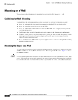
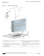
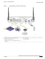
Chapter 3 Router and PoE Module Mounting Procedures Mounting on a Wall Perform the following steps to mount the router on a wall: Step 1 Step 2 Step 3 Step 4 Step 5 Step 6 Step 7 Select a location on the wall on which you wish to mount the router. Using Figure 3-1 as a reference, draw a horizontal line measuring 6.69 in. (17.0 cm) long. Make sure that the horizontal line is level. Drill two holes for the mounting screws, one at each end of the line. Use the drill bit size that is specified by the screw or hollow-wall anchor manufacturer. Measure 3.345 in. (8.5 cm) from either one of the screw holes to determine the midpoint between the two top mounting screws. From the midpoint, measure a vertical distance of 5.55 in. (14.1 cm) to determine the location for the bottom mounting screw, and then drill a hole. Anchor the screws into the wall, leaving 1/8 in. (0.32 cm) between the screw head and the wall for mounting the router. Hang the router on the screws as shown in Figure 3-2. Secure the screws into the latches of the mounting brackets. Place the power adapter on a horizontal surface. (See Figure 3-2.) Mounting the PoE Module on a Wall The PoE module can be mounted on a wall near the router. Figure 3-3 shows the location of the mounting brackets on the bottom panel of the PoE module. OL-5331-01 Cisco 850 Series and Cisco 870 Series Access Routers Hardware Installation Guide 3-5
-
 1
1 -
2
-
3
-
4
-
5
-
6
-
7
-
8
-
9
-
10
-
11
-
12
-
13
-
14
-
15
-
16
-
17
-
18
-
19
-
20
-
21
-
22
-
23
-
24
-
25
-
26
-
27
-
28
-
29
-
30
-
31
-
32
-
33
-
34
-
35
-
36
-
37
-
 38
38 -
 39
39 -
 40
40 -
 41
41 -
 42
42 -
 43
43 -
 44
44 -
 45
45 -
 46
46 -
 47
47 -
 48
48 -
49
-
50
-
51
-
52
-
53
-
54
-
55
-
56
-
57
-
58
-
59
-
60
-
61
-
62
-
63
-
64
-
65
-
66
-
67
-
68
-
69
-
70
-
71
-
72
-
73
-
74
-
75
-
76
-
77
-
78
-
79
-
80
-
81
-
82
-
83
-
84
-
85
-
86
-
87
-
88
-
89
-
90
-
91
-
92
 |
 |
