Cisco 877W Hardware Installation Guide - Page 54
Connecting to an Ethernet Switch, Step 1
 |
UPC - 882658019579
View all Cisco 877W manuals
Add to My Manuals
Save this manual to your list of manuals |
Page 54 highlights
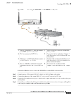
Connecting an External Ethernet Switch (Optional) Figure 4-7 Connecting to an Ethernet Switch Chapter 4 Router Cabling Procedures 1 LEFT 0 Cisco 871W LAN WAN FE4 0 FE3 1 FE2 2 FE1 3 FE4 RESET CONSOLE AUX +5,+12 VDC 1 RIGHT / PRIMARY 117972 SYSTEM RPS MODE STATUS UTIL DUPLX SPEED 1 1X 23 45 67 8 9 10 11 12 15X 2X 16X 2 1 1X 23 45 67 8 9 10 11 12 15X 2X 16X 1 Catalyst 3500 SERIES XL INLINE POWER 2 1 Yellow Ethernet cable connecting an external 2 Available port on the external Ethernet switch Ethernet switch to a built-in Ethernet switch port on the router Perform the following steps to connect the router to an external Ethernet switch: Step 1 Step 2 Step 3 Connect one end of the yellow Ethernet cable to a built-in Ethernet switch port on the router. Connect the other end of the cable to the available port on the Ethernet switch to add additional Ethernet connections. Turn on the Ethernet switch. 4-10 Cisco 850 Series and Cisco 870 Series Access Routers Hardware Installation Guide OL-5331-01
-
 1
1 -
2
-
3
-
4
-
5
-
6
-
7
-
8
-
9
-
10
-
11
-
12
-
13
-
14
-
15
-
16
-
17
-
18
-
19
-
20
-
21
-
22
-
23
-
24
-
25
-
26
-
27
-
28
-
29
-
30
-
31
-
32
-
33
-
34
-
35
-
36
-
37
-
38
-
39
-
40
-
41
-
42
-
43
-
44
-
45
-
46
-
47
-
48
-
 49
49 -
 50
50 -
 51
51 -
 52
52 -
 53
53 -
 54
54 -
 55
55 -
 56
56 -
 57
57 -
 58
58 -
 59
59 -
60
-
61
-
62
-
63
-
64
-
65
-
66
-
67
-
68
-
69
-
70
-
71
-
72
-
73
-
74
-
75
-
76
-
77
-
78
-
79
-
80
-
81
-
82
-
83
-
84
-
85
-
86
-
87
-
88
-
89
-
90
-
91
-
92
 |
 |
