Cisco 877W Hardware Installation Guide - Page 67
Connecting AC Adapters to the Router and to the PoE Module
 |
UPC - 882658019579
View all Cisco 877W manuals
Add to My Manuals
Save this manual to your list of manuals |
Page 67 highlights
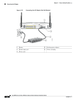
Chapter 4 Router Cabling Procedures Connecting the AC Adapter Figure 4-19 Connecting AC Adapters to the Router and to the PoE Module 1 1 LEFT 0 SN: XXXNNNNXXXX LAN FE0 FE1 FE2 FE3 Cisco 871W WAN FE4 RESET CONSOLE AUX +5,+12 VDC RIGHT / PRIMARY 2 PWR 7 0 1 2 3 To LAN 5 3 6 4 122351 1 Router 2 Ethernet cables on the PoE module 3 PoE module 4 PoE module power adapter 5 Router power adapter 6 PoE module power adapter plug 7 Router power adapter plug Perform the following steps to connect power to the router and to the PoE module: Step 1 Step 2 Step 3 Step 4 Connect one end of the power supply cable to the input jack of the router. Connect the other end of the power supply cable to the router power adapter. If a PoE module is connected to the router, connect the PoE module power adapter to the PoE module. Plug the power cord of the router power adapter into an electrical outlet. If a PoE module is connected to the router, plug the power cord for the PoE module into an electrical outlet. OL-5331-01 Cisco 850 Series and Cisco 870 Series Access Routers Hardware Installation Guide 4-23
-
 1
1 -
2
-
3
-
4
-
5
-
6
-
7
-
8
-
9
-
10
-
11
-
12
-
13
-
14
-
15
-
16
-
17
-
18
-
19
-
20
-
21
-
22
-
23
-
24
-
25
-
26
-
27
-
28
-
29
-
30
-
31
-
32
-
33
-
34
-
35
-
36
-
37
-
38
-
39
-
40
-
41
-
42
-
43
-
44
-
45
-
46
-
47
-
48
-
49
-
50
-
51
-
52
-
53
-
54
-
55
-
56
-
57
-
58
-
59
-
60
-
61
-
 62
62 -
 63
63 -
 64
64 -
 65
65 -
 66
66 -
 67
67 -
 68
68 -
 69
69 -
 70
70 -
 71
71 -
 72
72 -
73
-
74
-
75
-
76
-
77
-
78
-
79
-
80
-
81
-
82
-
83
-
84
-
85
-
86
-
87
-
88
-
89
-
90
-
91
-
92
 |
 |
